
Portable Power Supply Device

a power supply device and portable technology, applied in emergency power supply arrangements, secondary cells servicing/maintenance, cell components, etc., can solve the problems that the prior art portable power devices are generally not suited for continuous use in areas, and achieve the effects of large electrical power available, large capacity batteries, and maintaining portability

Inactive Publication Date: 2011-05-05
SCHROEDER KIRK +1
View PDF6 Cites 762 Cited by
  • Summary
  • Abstract
  • Description
  • Claims
  • Application Information

AI Technical Summary

Benefits of technology

[0016]By providing batteries within a battery housing which is readily separable from the inverter supported within the inverter housing, using mating electrical connectors between the housings, the portable power supply device of the present invention can accommodate much large capacity batteries while maintaining portability. The separable nature of the inverter housing from the battery housing further permits ready access to the batteries for charging or for interchanging the inverter housing between plural different battery housings which permits one set of batteries to be charged while a different set is in use. Thus, in addition to providing much larger electrical power available, the configuration of the power supply device of the present invention also permits continuous use by allowing simultaneous charging and use of the electrical power. Furthermore charging terminals are mounted externally on the inverter housing for ready access to connect to a charging device in a convenient manner without requiring the housings to be opened or separated in some form. The charging terminals are configured to permit ready connection to a wind or solar generator. Despite the large electrical power available in the device according to the present invention, portability is maintained by supporting the battery housing for rolling movement on the ground and by supporting the inverter housing above the battery housing for relative vertical sliding movement between a working position supported on the battery housing and a released position separated from the battery housing.

Problems solved by technology

The mounting configuration of the battery and the inverter within a common housing provide limited access for charging the batteries or for maintenance or variation of any configurations of the device.
Due to the limited power available and the poor mounting configuration of the components in the prior art, prior art portable power devices are generally not suited for continuous use in areas with large power requirements, for example power tools on a construction site.

Method used


Image

  • Portable Power Supply Device
  • Portable Power Supply Device
  • Portable Power Supply Device

Examples


Embodiment Construction

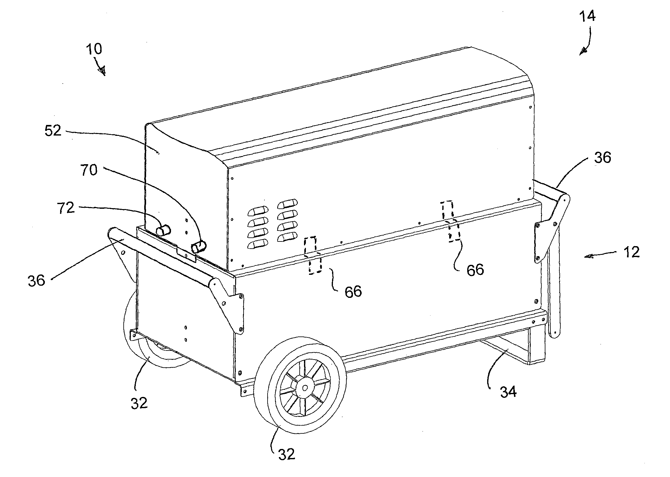
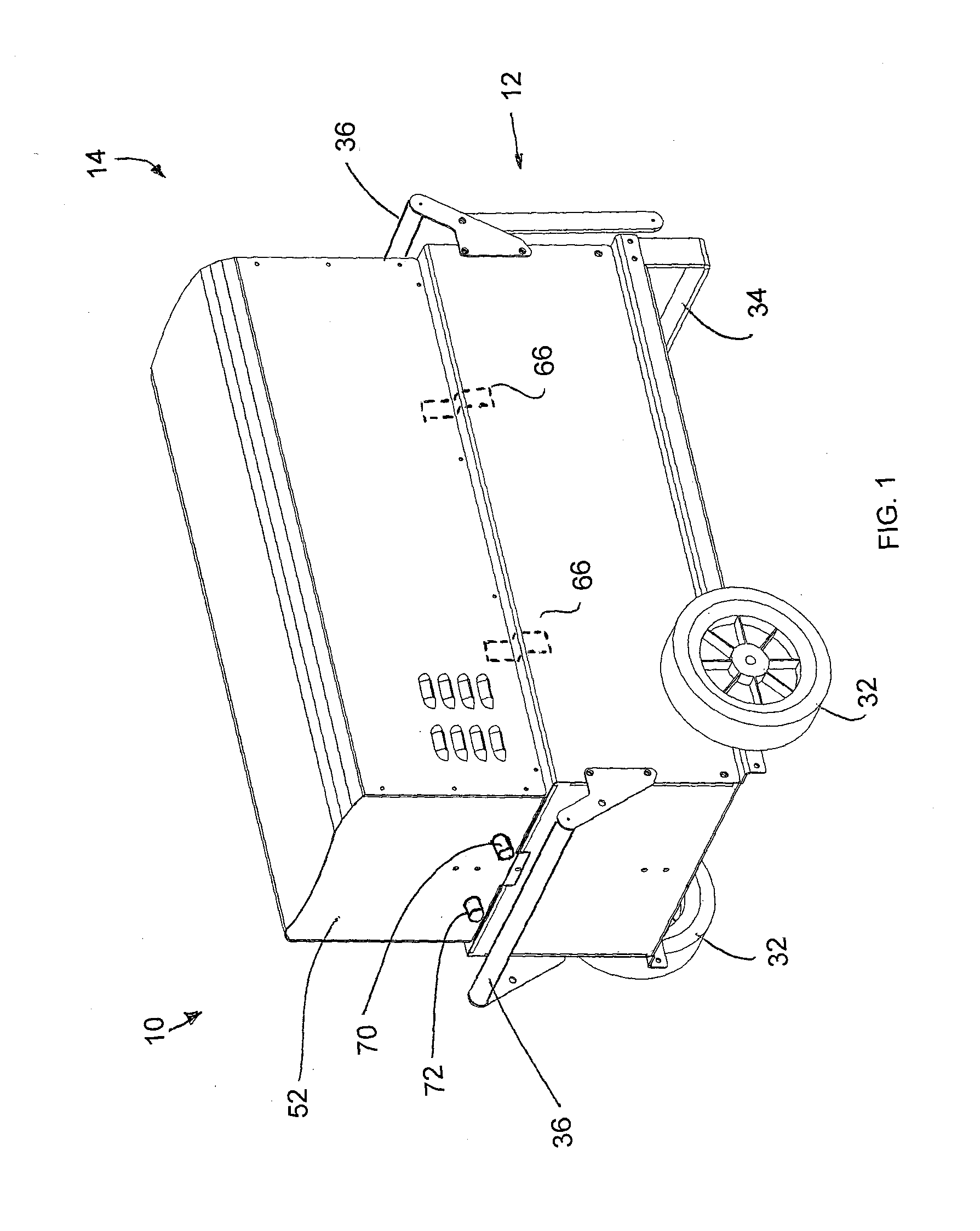
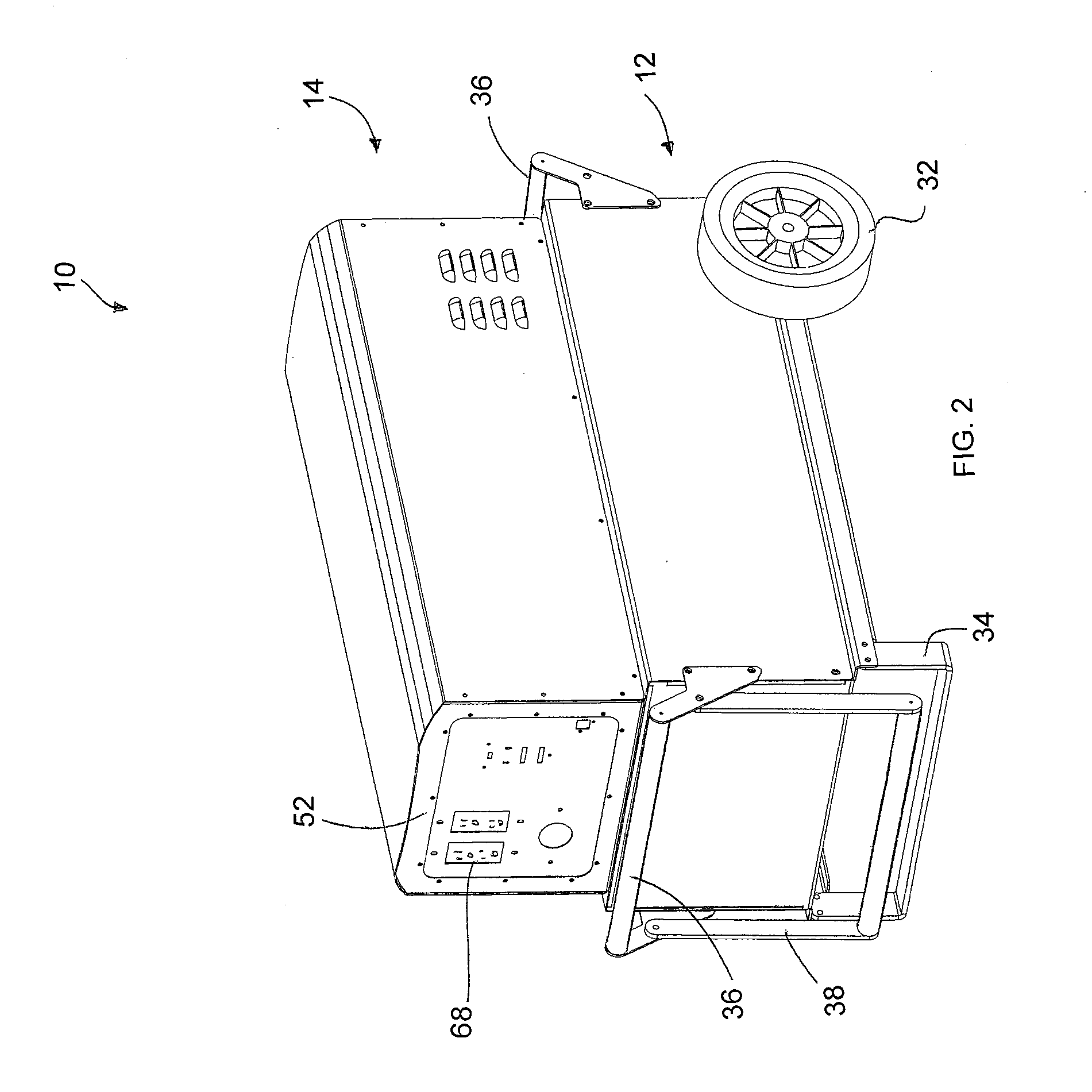
[0059]Referring to the accompanying figures there is illustrated a portable power supply device generally indicated by reference numeral 10. The device 10 is particularly suited for use in areas where no electrical grid power is available.

[0060]Although various embodiments of the device 10 are shown in the accompanying figures, the common features of all of the embodiments will first be described herein.

[0061]The device 10 generally comprises a battery housing 12 arranged to be supported for rolling movement on the ground and an inverter housing 14 which is supported on the battery housing so as to be readily separable therefrom.

[0062]The battery housing 12 is arranged to receive a plurality of batteries therein, for example automotive type batteries arranged to supply 12 volts of direct current. The housing 12 is rectangular in shape and includes a lower portion 16 and an upper portion 18 which receive the batteries 15 therebetween. The lower portion comprises a rectangular bottom ...


PUM


Abstract

A portable power supply device comprises a stackable battery housing locating a plurality of batteries therein and an inverter housing locating an inverter therein which is arranged to convert the direct current from the batteries to an alternating current. The inverter housing is readily separable from the battery housing such that one or more battery housings can be readily interchangeable to provide a constant supply of power and to allow a variety of charging configurations of the batteries. First electrical connectors on the battery housing and second electrical connectors on the inverter housing automatically connect the inverter to the batteries upon stacking of the inverter housing on the battery housing. Furthermore charging terminals are mounted externally on the inverter housing for ready access to connect to a charging device in a convenient manner without requiring the housings to be opened or separated form one another.

Description

[0001]This application claims priority benefits from U.S. provisional application No. 61 / 082,260 filed Jul. 21, 2008.FIELD OF THE INVENTION[0002]The present invention relates to a portable power supply device in which an electrical power inverter converts direct current power supplied from a plurality of batteries to an alternating current power supply in a portable configuration.BACKGROUND[0003]The use of portable power supply device is known to be desirable in locations where conventional grid power is unavailable, for example construction sites or remote areas.[0004]US publications 2007 / 0013340 belonging to Mattichak and 2007 / 0019453 belonging to Pierce disclose examples of portable power supply devices having limited application. In each instance, only low amounts of power are provided, typically for providing electrical power to a few basic essential devices in the event of a power failure. Insufficient power is provided for operating power tools on a construction site for exam...

Claims


Application Information

Patent Timeline
IPC IPC(8): H02J7/00H02J7/32H01M50/209H01M50/244H01M50/247H01M50/291H01M50/503H01M50/512
CPCH01M2/1022H01M2/1061H01M2/204H02M7/003H01M10/425H02J7/0042H01M10/4207Y02E60/10H01M50/209H01M50/512H01M50/247H01M50/291H01M50/503H01M50/244
Inventor SCHROEDER, KIRKFRIESEN, DION
Owner SCHROEDER KIRK
Learn More