
Automatic transmission and protection method thereof

a technology of automatic transmission and protection method, which is applied in the direction of fluid gearing, gearing, instruments, etc., can solve the problems of insufficient supply, seizure and breakage, and inability to determine the completion of the work appropriately

Inactive Publication Date: 2011-04-28
MITSUBISHI ELECTRIC CORP +2
View PDF10 Cites 6 Cited by
  • Summary
  • Abstract
  • Description
  • Claims
  • Application Information

AI Technical Summary

Benefits of technology

The patent describes a method to prevent damage to an automatic transmission by increasing the temperature of the oil used to cool it. This is particularly important when the oil is very cold, as this can cause delays in the transmission's activation. The method involves starting a process to increase the oil temperature and monitoring its progress until it reaches a predetermined level. This way, the oil can be heated up to the required level without causing damage to the transmission. The method can be applied to both new and existing transmissions.

Problems solved by technology

When the temperature of the ATF falls further so as to enter an extremely low temperature region, the ATF accumulates in a cooler hose connecting an ATF cooler to the automatic transmission and cannot be supplied sufficiently to the automatic transmission from the ATF cooler.
When an insufficient amount of ATF is supplied to the automatic transmission, seizure and breakage may occur in the frictional engagement elements and rotary elements.
Further, when the temperature is extremely low such that the ATF cannot be supplied to the automatic transmission from the ATF cooler, only the temperature of the ATF in the automatic transmission rises, and therefore, if a method of determining completion of the temperature increase promotion processing on the basis of the temperature of the ATF is employed, completion cannot be determined appropriately.

Method used


Image

  • Automatic transmission and protection method thereof
  • Automatic transmission and protection method thereof
  • Automatic transmission and protection method thereof

Examples


Embodiment Construction

tion.

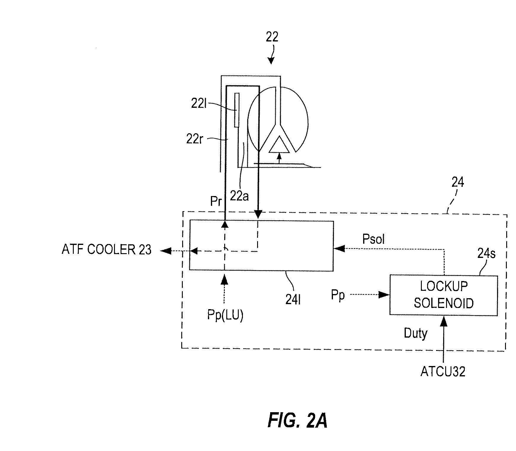
[0014]FIG. 2A is an illustrative view illustrating an un-lockup condition.

[0015]FIG. 2B is an illustrative view illustrating a lockup condition.

[0016]FIG. 3 is a flowchart showing the content of a protection control program executed on the automatic transmission by a transmission control unit.

DESCRIPTION OF THE PREFERRED EMBODIMENTS

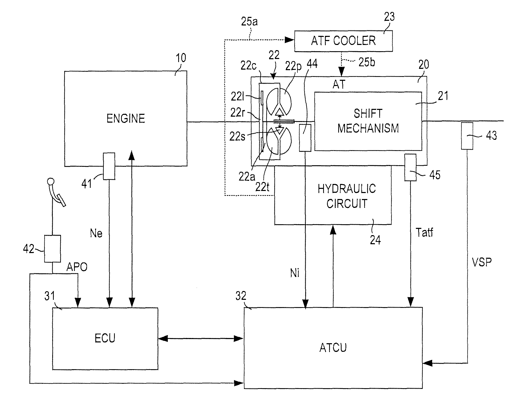
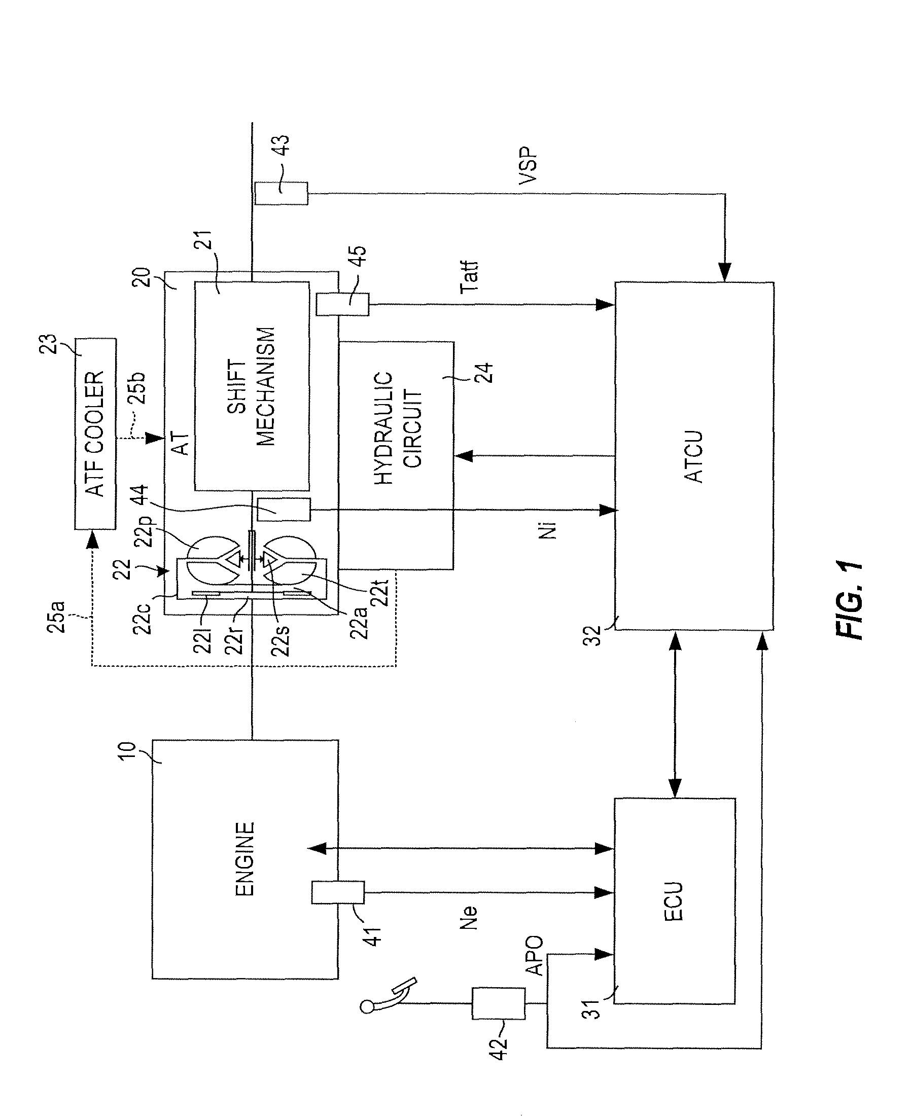
[0017]FIG. 1 shows an outline of the constitution of a vehicle including an automatic transmission according to an embodiment of this invention. The vehicle comprises an engine 10 and an automatic transmission (AT) 20. An output rotation of the engine 10 is varied by the automatic transmission 20 and then transmitted to drive wheels, not shown in the figure.

[0018]The automatic transmission 20 comprises a shift mechanism 21 and a torque converter 22. The shift mechanism 21 is a step shift mechanism constituted by a plurality of planetary gears, a plurality of frictional engagement elements (clutches, brakes), and so on and having first to seventh forw...


PUM


Abstract

When temperature increase promotion processing (for example, prohibiting lockup application and prohibiting shifts to a high gear position) is started while an initial value of an ATF temperature is in a low temperature region, an ATCU determines whether to terminate the temperature increase promotion processing on the basis of a current ATF temperature, and when the temperature increase promotion processing is started while the initial value of the ATF temperature is in an extremely low temperature region, the ATCU determines whether to terminate the temperature increase promotion processing on the basis of a duration of the temperature increase promotion processing. When the temperature increase promotion processing is determined to be complete, the ATCU terminates the temperature increase promotion processing.

Description

FIELD OF THE INVENTION[0001]This invention relates to control of an automatic transmission, and more particularly to protection control of an automatic transmission at an extremely low temperature.BACKGROUND OF THE INVENTION[0002]When an outside air temperature is low, leading to a reduction in the temperature of a working oil (to be referred to as “ATF” hereafter) of an automatic transmission, a viscosity of the working oil increases, causing delays in the engagement / disengagement of frictional engagement elements that contribute to shifts, such as clutches and brakes. As a result, shift shock and shift delays occur.[0003]To prevent this, JP2-96068U discloses a technique of prohibiting shifts to a highest gear position at a low temperature and waiting for a predetermined time to elapse following engine startup before canceling the prohibition of shifts to the highest gear position. According to this technique, by prohibiting shifts to the highest gear position, a rotation speed of ...

Claims


Application Information

Patent Timeline
Patent Type & Authority Applications(United States)
IPC IPC(8): F16H59/72F16H61/14
CPCB60W30/194F16H57/0413F16H61/16F16H61/143F16H59/72F16H59/44
Inventor KATO, NOBUHIDEMORIFUJI, NOBUHIKOYOSHIDA, TOYOTAROYAMAMOTO, TOSHIMITSU
Owner MITSUBISHI ELECTRIC CORP
Learn More