
Disposable diaper state detecting device and disposable diaper state monitoring system

a technology of state monitoring and diaper, which is applied in the direction of electric signalling details, signalling systems, instruments, etc., can solve the problems of limited absorbing capacity of the absorbing layer, irritation of the skin of the user, and difficulty in normal situations to observe whether the diaper has been wet, so as to achieve convenient use and low cost of using the device

Inactive Publication Date: 2011-04-28
XU FEI +1
View PDF13 Cites 47 Cited by
  • Summary
  • Abstract
  • Description
  • Claims
  • Application Information

AI Technical Summary

Benefits of technology

The technical problem to be solved in the present application is to aim at the technical problem of the existing product and provide a disposable diaper condition detecting device and monitoring system. Particularly, it provides a wireless network device and system to realize wireless urine-wetness induction and urine-wetness condition indication suitable for disposable diapers. The system can effectively remind caretakers to carry out the necessary caring tasks without disturbing other people. It is convenient to use, reliable, clean and hygienic, and relatively low in cost of using the device.
The disposable diaper condition detecting device disclosed in the present application has the following advantages:
Secondly, the sensor is far away from the skin in use so that it can prevent erroneous activation caused by sweating or light excretion.
Thirdly, the sensor connected to the interlayer of the diaper is disposable. The sensor is discarded together with the diaper after use. This ensures a clean and hygienic usage.
Finally, the alarm and the sensor are separable. The alarm can be used repeatedly. This effectively reduces the cost of using the device.
The disposable diaper condition monitoring system of the present application has the benefits in that:(i) It is a wireless induction network system. The position of the sensors does not affect the alarm effect. This can effectively solve the problem that the normal acousto-optic alarm system is not suitable for hospitals and care centers.(ii) It is easy to establish a networking and centralized wireless system suitable for use in organized and sized application.(iii) The sensor is provided with call function to solve special needs of different patients, or to be used in emergency situations.(iv) Voice intercom function is provided on the wireless display in the patient's room and the data terminal at the caring center. This is a direct and effective way of communication. This is an important function of the network system.(v) The data terminal can further be connected to a computer for processing all the data of the sensors in the system. This can realize the recording of the condition of elders / patients and raise the quality of caring and level of service of the nursing organizations.

Problems solved by technology

In one aspect, the absorbing capacity of the absorbing layer is limited.
The gas generated by the decomposition of urine inside the absorbing layer may remain in the diaper for a long time causing irritation of the skin of the user.
Since a disposable diaper is relatively tight, it is difficult in normal situation to observe whether the diaper has been wetted.
Particularly when the caretakers are rather busy, it is easy to neglect the changing of the wetted diaper that causes skin problem of the user.
However, the existing stand-alone electronic urine-wetness acousto-optic alarm devices cannot satisfy the need.
Acousto-optic alarm can easily be neglected in a relatively noisy and busy environment.
Also, if the alarm is too loud, it can easily disturb other patients.
In reality, this normally does not work.

Method used


Image

  • Disposable diaper state detecting device and disposable diaper state monitoring system
  • Disposable diaper state detecting device and disposable diaper state monitoring system
  • Disposable diaper state detecting device and disposable diaper state monitoring system

Examples


first embodiment

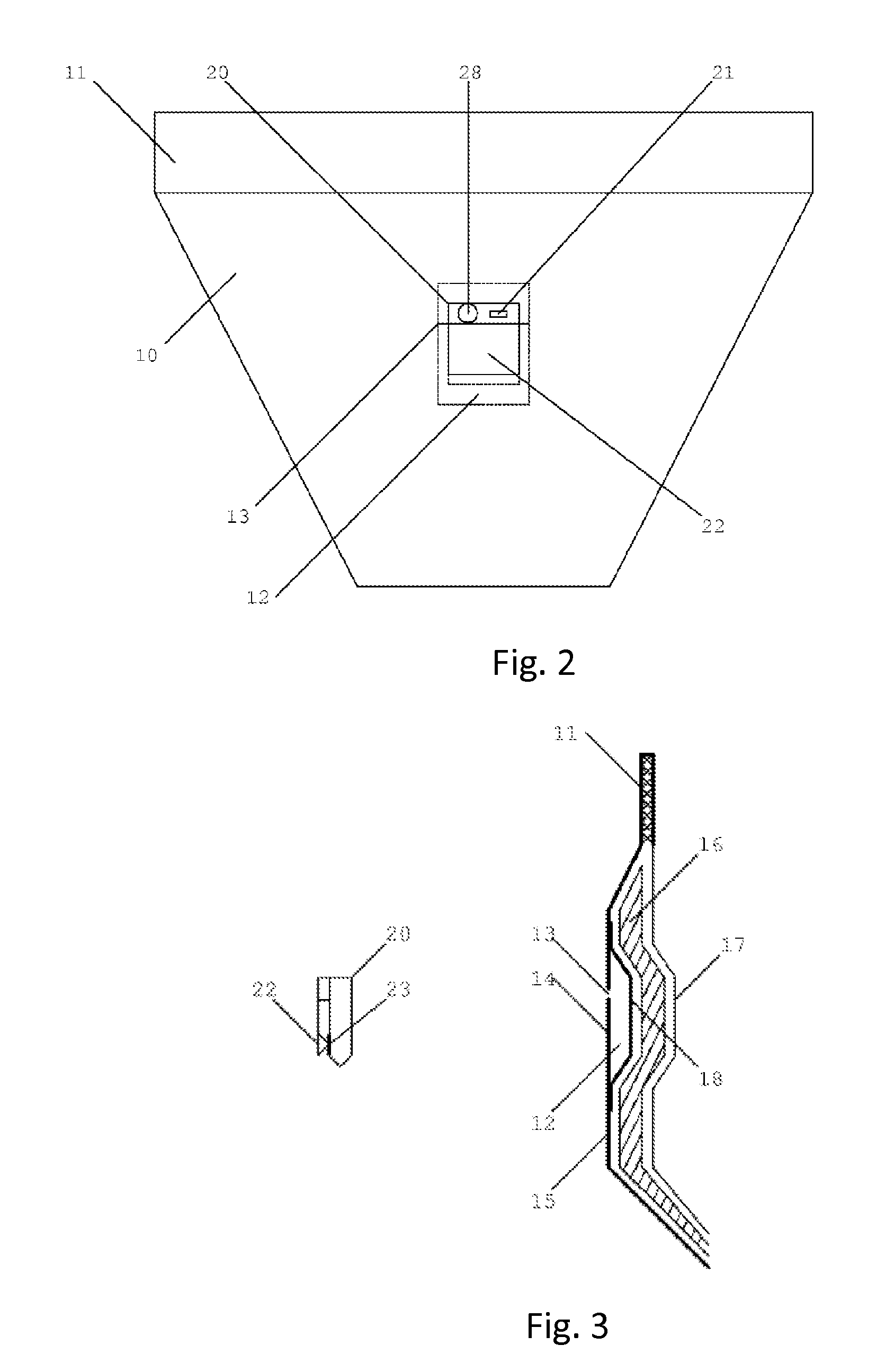
FIG. 2 is an illustrative diagram of the application of the disposable diaper condition detecting system of the wireless sensor 01 of the present application.

It is necessary to indicate that the present application provides a disposable diaper condition detecting system, including a disposable diaper, an induction device and an alarming device;the disposable diaper comprising an outer layer, an interlayer and an inner layer;the induction device being disposed on the outer layer, or between the outer and inner layers, for detecting urine-wetness condition of the disposable diaper and generating a urine-wetness condition induction signal;the alarming device being integrally formed with the induction device, or combinable with or separable from the induction device, andthe alarming device being electrically coupled to the induction device when combined together for sounding alarm according to the urine-wetness condition induction signal generated by the induction device.

Since the dispo...

second embodiment

FIG. 7 shows the front view (3a1) of the sensing input device, and the rear and front views (3b1 and 3b2) of the urine-wetness alarm of the wireless sensor 01 of the present application. The positioning notches 34a, 35a at the outer edge of the insulating gasket and the positioning catches 34b, 35b on the alarm are clearly illustrated in FIG. 7. The dimensions of the positioning notches 34a, 35a and the positioning reverted catches 34b, 35b are different (the dimensions of positioning notch 35a and the positioning catch 35b are bigger). This difference in structure can prevent the possibility of incorrect coupling between the sensing input device and the urine-wetness alarm. The sensing electrodes 32a associate with the contact electrodes 32b. When the sensing input device and the urine-wetness alarm are in an assembled condition, the sensing electrodes 32a can be electrically coupled to the contact electrodes 32b. In the rear view (3b1) of the urine-wetness alarm, it can be seen th...

third embodiment

In practice, the wireless sensors 01 can have many different designs to realize the cooperation of the electronic wetness-sensing diapers. FIG. 13 shows the electronic induction diaper and urine-wetness alarm of the wireless sensor 01. A side cross sectional view of the electronic induction diaper is denoted by reference numeral 50. Reference numeral 52 represents the outer layer (anti-leakage layer) of the diaper 50. Reference numeral 53 represents the inner layer (dry layer) of the diaper 50. Reference numeral 55 represents the interlayer being adhered to the outer layer and the inner layer at the waistline 51 to prevent the leakage of urine. The above-mentioned structures are the same as an ordinary diaper. The difference is that the diaper 50 in the present embodiment further includes a urine-wetness induction wires 56 located between the interlayer 55 and the outer layer 52 (in practical application, it can be located between the dry layer 53 and the interlayer 55) and extended...


PUM


Abstract

A disposable diaper condition detecting device includes a disposable diaper, an induction device (01; 56) and an alarming device (20; 60). The disposable diaper includes an outer layer (15; 80), an interlayer (16) and an inner layer (17). The induction device (01; 56) is provided on the outer layer (15; 80) or provided between the outer layer (15; 80) and the inner layer (17) of the disposable diaper. The induction device (01; 56) is used to detect the urine-wetness condition of the disposable diaper and to produce the urine-wetness condition induction signal. The alarming device (20; 60) may be integrated with the induction device (01; 56), or may be combined with the induction device (01; 56) or may be separated from the induction device (01; 56). A disposable diaper condition monitoring system includes a disposable diaper condition detecting device and a disposable diaper condition displaying device (02). The disposable diaper condition display device (02) is used to display the disposable diaper condition information based on the urine-wetness condition signal or the urine-wetness alarming signal transmitted from the disposable diaper condition detecting device.

Description

CROSS-REFERENCE TO RELATED APPLICATIONSThis application claims priorities of Chinese patent application No. 200810142520.0 filed on Jul. 28, 2008, Chinese patent application No. 200810142519.8 filed on Jul. 28, 2008, Chinese patent application No. 200810142331.3 filed on Aug. 8, 2008, Chinese patent application No. 200810142385.x filed on Aug. 18, 2008, and Chinese patent application No. 200920129698.1 filed on Feb. 1, 2009, the entire contents of which are hereby incorporated by reference.The present application relates to a disposable diaper condition detecting device and monitoring system, and particularly to a wireless network device and system to realize wireless urine-wetness induction and urine-wetness condition indication suitable for disposable diapers.BACKGROUNDDisposable diapers (or paper diapers) are hygiene goods. They are very popular at home, in hospitals and at care centers. Disposable diapers are discarded after use and no doubt are more hygienic and convenient rela...

Claims


Application Information

Patent Timeline
Patent Type & Authority Applications(United States)
IPC IPC(8): G08B1/08G08B21/00
CPCA61F13/42
Inventor XU, FEIHUANG, GENG
Owner XU FEI
Learn More