Wireless power feeder, wireless power transmission system, and table and table lamp using the same

a technology of wireless transmission system and feeder, which is applied in the direction of transformer/inductance circuit, basic electric elements, inductance, etc., can solve the problem of not being able to feed big electric power, and achieve the effect of easy control of transmission power

Active Publication Date: 2011-04-28
TDK CORPARATION
View PDF11 Cites 40 Cited by
  • Summary
  • Abstract
  • Description
  • Claims
  • Application Information

AI Technical Summary

Benefits of technology

[0025]According to the present invention, it is possible to easily perform control of transmission power in wireless power feeding of a magnetic field resonance type.

Problems solved by technology

The type (B) utilizing radio wave is available in a long range; however, it cannot feed big electric power.

Method used


Image

  • Wireless power feeder, wireless power transmission system, and table and table lamp using the same
  • Wireless power feeder, wireless power transmission system, and table and table lamp using the same
  • Wireless power feeder, wireless power transmission system, and table and table lamp using the same

Examples


Embodiment Construction

[0034]A preferred embodiment of the present invention will be described below with reference to the accompanying drawings.

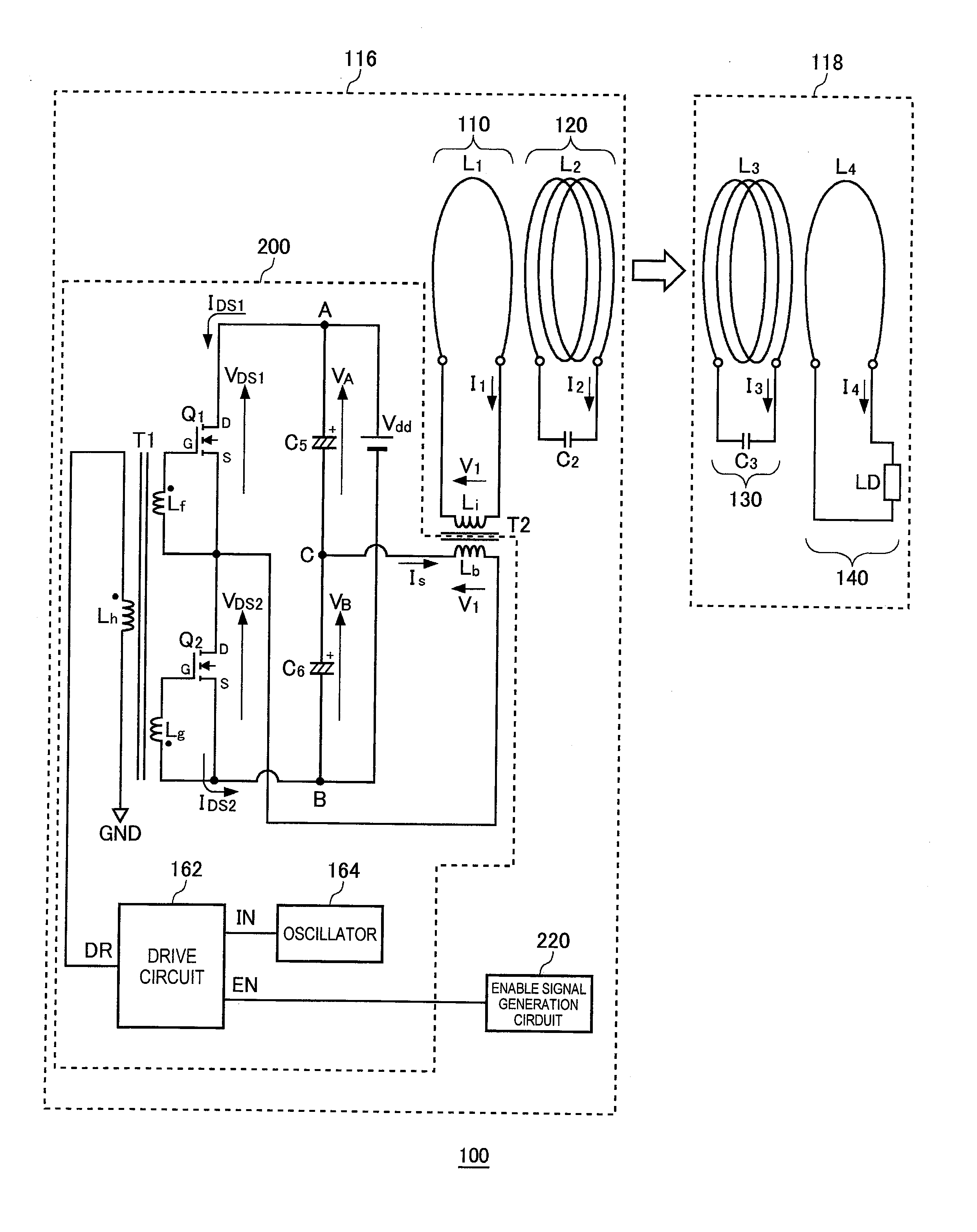
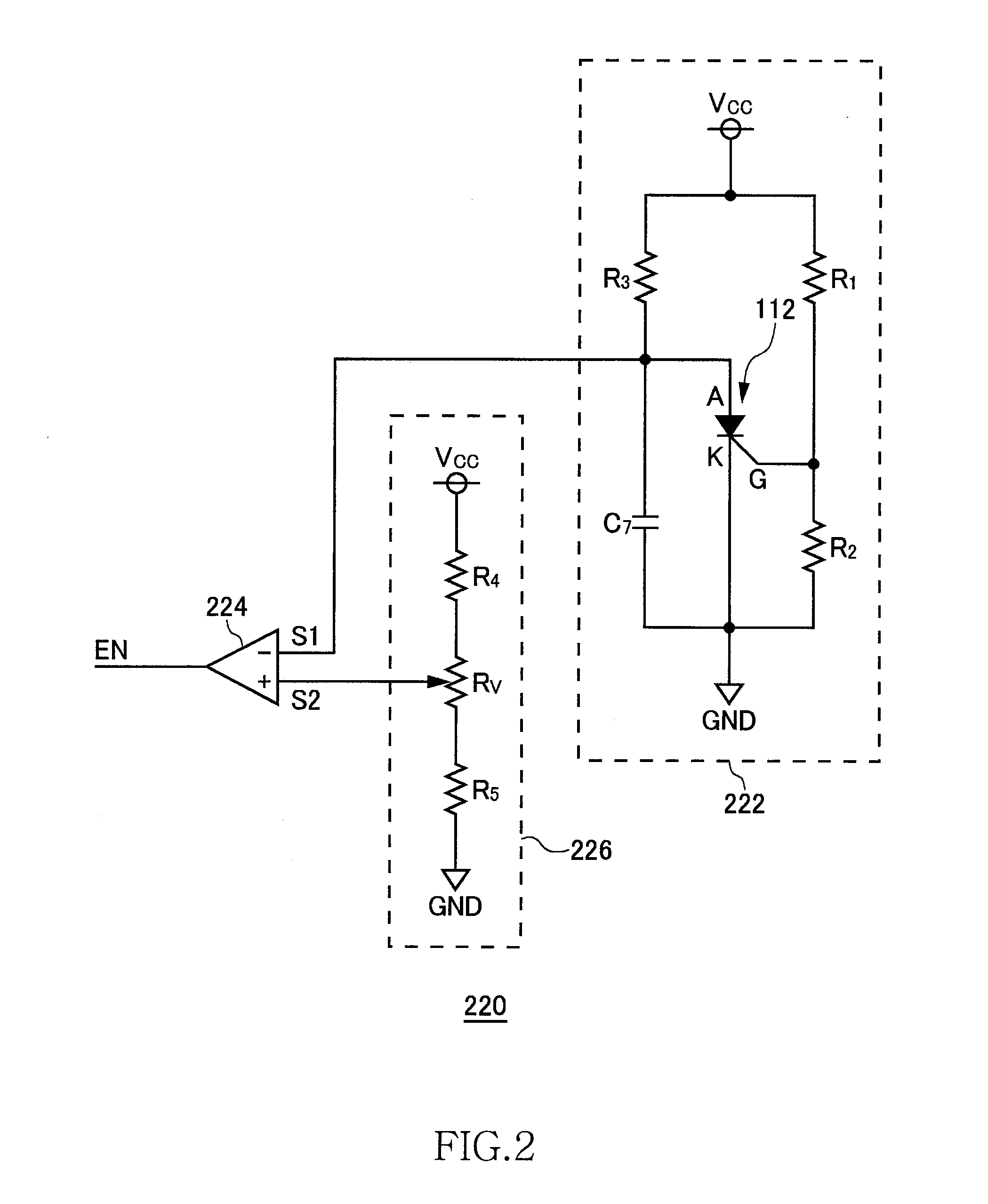
[0035]FIG. 1 is a system configuration view of a wireless power transmission system 100. The wireless power transmission system 100 includes a wireless power feeder 116 and a wireless power receiver 118. The wireless power feeder 116 includes, as basic components, a power transmission control circuit 200, an exciting circuit 110, a feeding coil circuit 120, and enable signal generation circuit 220. The wireless power receiver 118 includes a receiving coil circuit 130, and a loading circuit 140.

[0036]A distance of about 0.2 to 1.0 m is provided between a feeding coil L2 of the feeding coil circuit 120 and a receiving coil L3 of the receiving coil circuit 130. The wireless power transmission system 100 mainly aims to feed AC power from the feeding coil L2 to receiving coil L3 by wireless. The wireless power transmission system 100 according to the present embodimen...


PUM


Abstract

Power is fed from a feeding coil to a receiving coil by magnetic resonance. A drive circuit outputs an IN signal generated by an oscillator as a DR signal to alternately turn ON/OFF switching transistors at a resonance frequency, whereby AC current is fed to the feeding coil, and then the AC current is fed from the feeding coil to the receiving coil. An enable signal generation circuit generates an EN signal at a frequency lower than the resonance frequency. The drive circuit outputs the DR signal only while the EN signal assumes a high level. Transmission power from a wireless feeder to a wireless receiver is controlled by adjusting the duty ratio of the EN signal.

Description

BACKGROUND OF THE INVENTION[0001]1. Field of the Invention[0002]The present invention relates to a wireless AC power feeding and, more particularly, to power control thereof.[0003]2. Description of Related Art[0004]A wireless power feeding technique of feeding power without a power cord is now attracting attention. The current wireless power feeding technique is roughly divided into three: (A) type utilizing electromagnetic induction (for short range); (B) type utilizing radio wave (for long range); and (C) type utilizing resonance phenomenon of magnetic field (for intermediate range).[0005]The type (A) utilizing electromagnetic induction has generally been employed in familiar home appliances such as an electric shaver; however, it can be effective only in a short range of several centimeters. The type (B) utilizing radio wave is available in a long range; however, it cannot feed big electric power. The type (C) utilizing resonance phenomenon is a comparatively new technique and is...

Claims


Application Information

Patent Timeline
Patent Type & Authority Applications(United States)
IPC IPC(8): H02J17/00
CPCH02J5/005H02J50/12
Inventor URANO, TAKASHI
Owner TDK CORPARATION
Why Eureka
Try Eureka