
Humidification apparatus having RFID tag sensor at patient end of gas pathway

a technology of rfid tag and sensor, which is applied in the direction of ohmic-resistance heating, inhalators, other medical devices, etc., can solve the problems of gas supply to patients, impaired performance of the entire humidification and breathing system, and dependence on the correct positioning of temperature sensors

Active Publication Date: 2011-04-21
FISHER & PAYKEL HEALTHCARE LTD
View PDF28 Cites 56 Cited by
  • Summary
  • Abstract
  • Description
  • Claims
  • Application Information

AI Technical Summary

Benefits of technology

[0009]It is an object of the present invention to attempt to provide a patient interface which goes some way to overcoming disadvantages in the prior art or which will at least provide the industry with a useful choice.

Problems solved by technology

A disadvantage of this type of temperature interface system is the dependency on the correct positioning of the temperature sensors.
Incorrect placement or connection of the temperature sensors can lead to impaired performance of the entire humidification and breathing system.
A further disadvantage is that gases may be supplied to the patient at a pressure / humidity combination which is inappropriate.
However, these adjustments often have no direct or intuitive relationship with the actual physical parameters they are intended to control.
Often the manual controls indirectly and undesirably adjust the required gases outlet temperature (by adjusting the power to the humidifier chamber heater plate), or the power to a heater wire provided within the conduit connecting the humidifier to patient (by altering the current flowing through the heater wire), or both.
This is because insufficient gases humidity can lead very quickly to dehydration of the patient's airways.

Method used


Image

  • Humidification apparatus having RFID tag sensor at patient end of gas pathway
  • Humidification apparatus having RFID tag sensor at patient end of gas pathway
  • Humidification apparatus having RFID tag sensor at patient end of gas pathway

Examples


Embodiment Construction

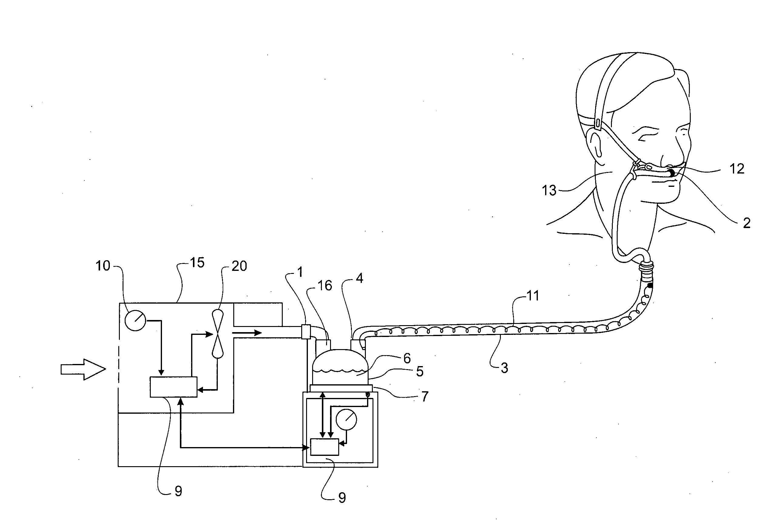
[0089]A breathing circuit for the delivery of heated, humidified gases to a patient or other user requiring heated humidified gases at a pressure above atmospheric is described below. The breathing circuit incorporates a sensing mechanism by which system parameters such as temperature, pressure, gases flow rate, humidity and gas composition can be measured at or close to the point at which the gases are delivered to a patient or user using the system. The preferred form of the sensing mechanism is lightweight and small in size, and is therefore very suitable for use at the patient end of a breathing circuit, where additional weight and bulk can add to patient discomfort and increase the chances of non-compliance with a treatment regime. In the most preferred form described below, the sensing mechanism also serves to identify the individual component of the breathing circuit in which it is embedded or attached. The invention as described is suitable for both RH and OSA, and can be us...


PUM


Abstract

A breathing circuit for delivering heated, humidified gases to a patient for medical purposes is described, comprising a humidifier chamber holding a quantity of water, a blower unit that delivers a pressurised gases stream to the chamber inlet, and a control system that adjusts output parameters of the breathing circuit, the circuit including a heater plate which heats the water in the chamber so that gases flowing through the chamber become heated and humidified, the circuit also including a gases transportation pathway and patient interface to convey heated humidified gases to a patient, the gases transportation pathway including an RFID tag located at the patient end which senses a parameter of the gases passing through the pathway, the control system including an RFID interrogator interrogating and receiving data relating to the sensed parameter from the RFID tag in real time, and adjusting the output parameters of the breathing circuit accordingly.

Description

FIELD OF THE INVENTION[0001]This invention relates a sensing system and component identification system, and particularly to a sensing and component identification system for use in a medical environment which allows parameters of therapeutic gases supplied to a patient to be measured.SUMMARY OF PRIOR ART[0002]A number of products are known in the art for measuring the temperature of gases being supplied to a patient as well as providing feedback to the gas humidification system. One common way of controlling humidification systems is to measure the temperature of gas at two points along the conduit used to supply gas to the patient, and using the temperature data gathered to adjust the power output accordingly. For example, a first temperature sensor is inserted adjacent to the output of the humidifier chamber and a second temperature sensor is located proximal to the patient (e.g. in or around the patient interface), both measuring temperature data and feeding this back to a centr...

Claims


Application Information

Patent Timeline
IPC IPC(8): A61M16/16
CPCA61M16/06A61M16/161A61M16/1075A61M16/16A61M2016/0027A61M2016/0033A61M2016/1025A61M2205/18A61M2205/276A61M2205/3368A61M2205/3569A61M2205/3592A61M2205/581A61M2205/583A61M2205/6018A61M2205/6054A61M2210/0618A61M16/0069A61M16/109A61M16/1095A61M16/0683A61M16/0875
Inventor SOMERVELL, ANDREW ROBERT DONALDALAMI, NORDYNCHEUNG, DEXER CHI LUNQUILL, CHRISTOPHER SIMON JAMES
Owner FISHER & PAYKEL HEALTHCARE LTD
Learn More