Magnetically Coupled Battery Charging System

a battery charging and magnetic coupling technology, applied in electric vehicles, electric power, transportation and packaging, etc., can solve problems such as difficulty, reducing power transfer efficiency, and unable to achieve tight magnetic coupling

Active Publication Date: 2011-04-14
III HLDG 7
View PDF61 Cites 34 Cited by
  • Summary
  • Abstract
  • Description
  • Claims
  • Application Information

AI Technical Summary

Benefits of technology

[0069]In certain embodiments, the system further includes an integrator configured to vary a control signal supplied to the oscillator based on the signal provided by the phase comparator, thereby adjusting the oscillator such that there is about a ninety degree phase shift between the oscillator output and the resonant circuit output, thereby maintaining the drive signal to the resonant circuit at about the resonant freq...

Problems solved by technology

However, difficulty arises when attempting to provide a magnetic power source device that can couple with a variety of receiving devices without utilizing a close and predetermined physical relationship.
In other words, when the precise physical relationship between the primary and the secondary is not known, tight magnetic coupling may not be achieved.
For example, much of the magnetic flux produced by the primary winding may not be coupled to the secondary winding, thereby reducing the efficiency of power transfer and making the task of creating a sufficiently strong magnetic field in...

Method used


Image

  • Magnetically Coupled Battery Charging System
  • Magnetically Coupled Battery Charging System
  • Magnetically Coupled Battery Charging System

Examples


Embodiment Construction

)

[0138]Embodiments of the present technology relate to systems and methods for inductively charging batteries. While certain embodiments are described in detail, the present inventions are not limited to such embodiments, rather, one skilled in the art will understand that the teachings herein are applicable to many types of battery powered devices that can benefit from the inductive charging systems and methods disclosed herein.

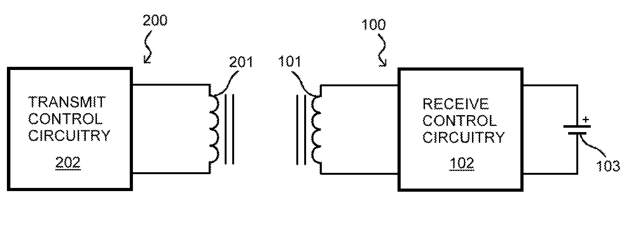
[0139]Referring to FIG. 1, a basic magnetically coupled battery charging system comprises transmit circuitry 200 and rechargeable battery assembly 100. Transmit circuitry 200 includes transmit (primary) coil 201 driven by transmit control circuitry 202, which produces an alternating current in coil 201. A portion of the magnetic field responsively generated by transmit coil 201 couples to receive (secondary) coil 101. The induced current in coil 101 passes through receive control circuitry 102 on the way to storage cell 103. Together, receive coil 101 and re...


PUM


Abstract

Inductively coupled battery charging systems and methods are provided. Transmit circuitry can include a transmit coil operatively part of a transmit resonant circuit that exhibits resonance at a transmit resonant frequency and an unloaded Q value of at least about 20. Transmit coil can generate a magnetic field at about the transmit resonant frequency. Rechargeable battery assembly can include a receive coil configured to receive inductively coupled current, and circuitry configured to rectify the current and communicate charging power to a storage cell. Receive coil can be part of a receive resonant circuit that exhibits resonance at about the transmit resonant frequency and an unloaded Q value of at least about 10. Transmit circuitry can include multiple transmit coils and can selectively discontinue production of alternating current in the coils generating fields that are not most strongly coupled to the receive coil.

Description

CROSS-REFERENCE TO RELATED APPLICATIONS / INCORPORATION BY REFERENCE[0001]U.S. Pat. No. 5,623,550 issued to Killion on Apr. 22, 1997 is incorporated herein by reference in its entirety.[0002]U.S. Pat. No. 7,206,426 issued to Julstrom et al. on Apr. 17, 2007 is incorporated herein by reference in its entirety.FEDERALLY SPONSORED RESEARCH OR DEVELOPMENT[0003][Not Applicable]MICROFICHE / COPYRIGHT REFERENCE[0004][Not Applicable]BACKGROUND OF THE INVENTION[0005]An electrical transformer transfers power from a primary winding to a secondary winding through the interaction of the windings' magnetic fields, with no conductive electrical contact. For many years, the notion of transferring power magnetically from a primary winding to a physically separable secondary winding has intrigued inventors. Reasons for coupling power magnetically include the safety and convenience of avoiding open electrical contacts and degradation that can afflict those contacts.[0006]Such technology has been utilized ...

Claims


Application Information

Patent Timeline
IPC IPC(8): H02J7/00
CPCH02J7/025H02J7/0044H02J50/40H02J50/80H02J50/90H02J50/12H02J50/70H02J50/005H02J7/00
Inventor JULSTROM, STEPHEN D.MONROE, TIMOTHY S.
Owner III HLDG 7
Why Eureka
Try Eureka