Aircraft gear caddy

a technology for aircraft and gear, applied in the field of aircraft gear caddy, can solve the problems of unnecessary time delay and effort of medical personnel, occupying valuable floor space, and affecting the service life of aircraft, etc., and achieves the effects of convenient use, freeing up valuable floor/deck space, and being easy to maintain

Inactive Publication Date: 2011-04-14
MACIA WILLIAM PATRICK
View PDF18 Cites 3 Cited by
  • Summary
  • Abstract
  • Description
  • Claims
  • Application Information

AI Technical Summary

Benefits of technology

[0008]The present invention provides advantages and alternatives over the prior art by providing an equipment storage apparatus which is easy to use, provides secure attachment to an air frame or other vehicle or equipment, meets air worthiness standards, frees up the valuable floor / deck space in the passenger cabin, and is inexpensive and easy to maintain.
[0009]More particularly, the invention resides in the ability to secure equipment yet allow it to be easily and safely accessed during flight through the use of a novel equipment pack utilizing novel attachment means to attach same to the bulkhead walls, chair or crew bench backrests, ceiling mounts, interior hatch / door walls, walls, and the like.
[0010]One object of the present invention is an aircraft gear caddy removably securely fixable to the bulkhead or other interior portion of an aircraft for storage and retrieval of materials during flight comprising in cooperative combination: a gear caddy unit consisting of; a front panel having a substantially rectangular shape with first and second sides and first and second ends, and having at least one gear securing pocket having a gear securable closure and closure device fixedly attached to said front panel; a rear panel having a substantially rectangular shape, of complimentary dimensions to said front panel with first and second sides and first and second ends, said first and second sides and said first end of said front panel and said rear panel being fixedly connected forming a sleeve with a sealable opening at said second end; a center strap fixedly attached down the longitudinal center line of said rear panel having a plurality of belt loop like openings; first and second fixedly attached side straps located parallel to and near each of said sides in having a plurality of belt loop like opening positioned complimentary to said center strap, said first and said second side straps further having a proximal and a distal end and each end terminating in a loop having a D-ring fixed attached therewith; a plurality of T-shape mounting devices removably insertable into a desired belt loop like opening of said center strap and a complimentary belt loop like opening in one said side strap of said gear caddy unit consisting of; a body comprising at least one layer of elastic strap having a proximal end to which is fixedly attached a cross member comprising an outer sleeve having a stiffening member permanently mounted therein, and a distal end having a loop fixedly attaching a mounting hook and further having fixedly mounted a loop of cord allowing stretching of said body thereby allowing mounting said mounting hook to an aircraft member; a substantially rigid panel removably mounted within said sleeve providing a shape substantially complimentary to the aircraft shape at the aircraft gear caddy mounting position; and an adjustable security strap fixedly mounted to each of said D-rings; thereby allowing for the removably secure mounting of said gear caddy unit to the interior of an aircraft.
[0011]Another object of the present invention is an aircraft gear caddy removably securely fixable to the bulkhead or other interior portion of an aircraft for storage and retrieval of materials during flight comprising in cooperative combination: a gear caddy unit consisting of; a front panel having a substantially rectangular shape with first and second sides and first and second ends, and having at least one gear securing pocket having a gear securable closure and closure device fixedly attached to said front panel; a rear panel having a substantially rectangular shape, of complimentary dimensions to said front panel with first and second sides and first and second ends, said first and second sides and said first end of said front panel and said rear panel being fixedly connected forming a sleeve with a sealable opening at said second end; a center strap fixedly attached down the longitudinal center line of said rear panel having a plurality of belt loop like openings; first and second fixedly attached side straps located parallel to and near each of said sides in having a plurality of belt loop like opening positioned complimentary to said center strap, said first and said second side straps further having a proximal and a distal end and each end terminating in a loop having a D-ring fixed attached therewith; a plurality of T-shape mounting devices removably insertable into a desired belt loop like opening of said center strap and a complimentary belt loop like opening in one said side strap of said gear caddy unit, further defined as having a portion of said plurality of T-shape mounting devices on each of side sides of said gear caddy unit, consisting of; a body comprising at least one layer of elastic strap having a proximal end to which is fixedly attached a metal cross member, and a distal end having a loop fixedly attaching a mounting hook and further having fixedly mounted a loop of cord allowing stretching of said body thereby allowing mounting said mounting hook to an aircraft member; a substantially rigid panel removably mounted within said sleeve providing a shape substantially complimentary to the aircraft shape at the aircraft gear caddy mounting position; and an adjustable security strap fixedly mounted to each of said D-rings; thereby allowing for the removably secure mounting of said gear caddy unit to the interior of an aircraft.
[0012]A further object of the present invention is providing an aircraft gear caddy that may be adapted to various aircraft mounting positions and various aircraft models by changing the removably mounted substantially rigid panel to one having an aircraft compatible shape suitable for the aircraft or aircraft mounting location.

Problems solved by technology

This creates unnecessary time delay and effort by medical personnel.
In addition, the lashed containers take up valuable floor space and get in the way of both patients and medical personnel.

Method used


Image

  • Aircraft gear caddy
  • Aircraft gear caddy
  • Aircraft gear caddy

Examples


Embodiment Construction

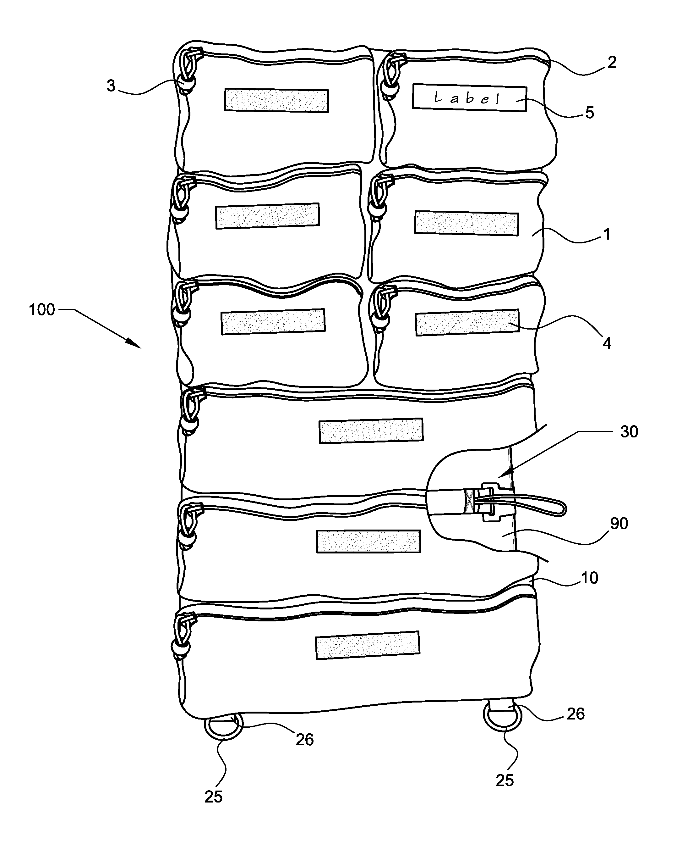
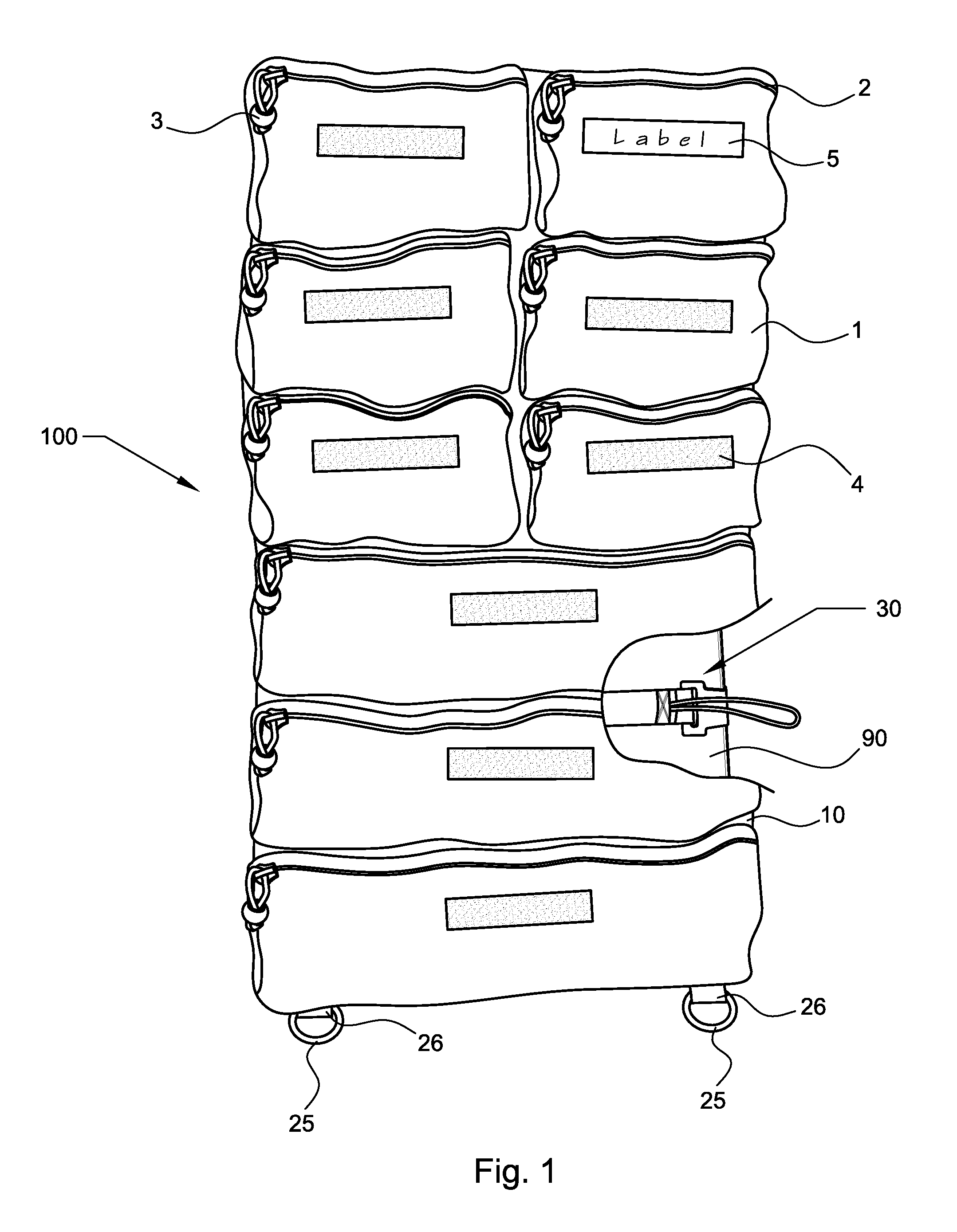
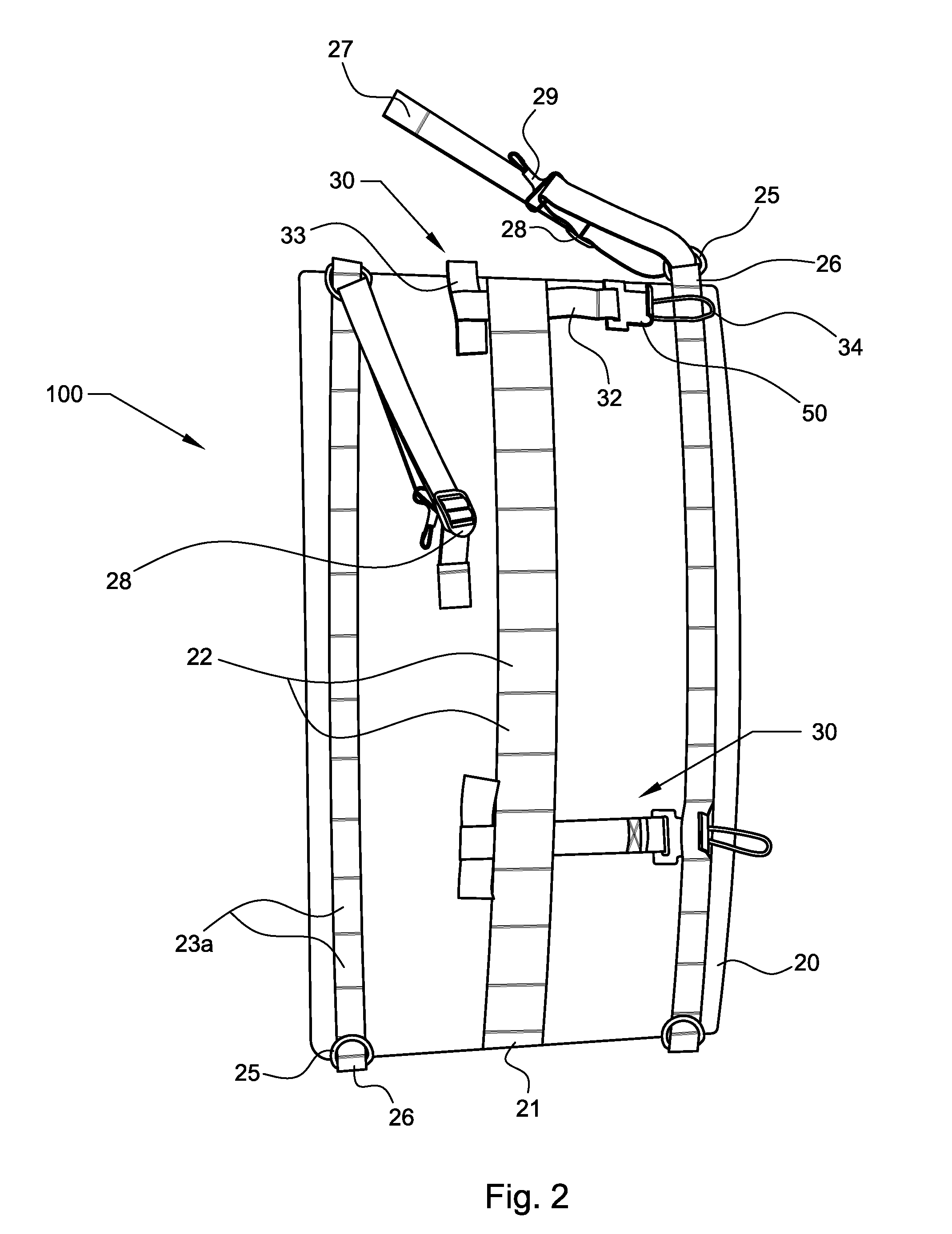
[0026]Reference will now be made to the drawings, wherein to the extent possible like reference numerals are utilized to designate like components throughout the various views. Referring to FIG. 1, there is presented a front view of a preferred embodiment of the claimed aircraft gear caddy 100 comprising a front panel 10 having a substantially rectangular shape with first and second sides and first and second ends, and having at least one, and preferably a plurality, of gear securing pockets 1 fixedly attached to said front panel 10. Each of said at least one gear securing pockets 1 having gear securable closure 2 and closure means 3. Further, each of said at least one gear securing pockets 1 has a label attachment device 4 for removably securing a label 5. Also shown in FIG. 1 are D-rings 25 fixedly attached to back panel 20 (see FIG. 2) by attachment loop 26. Further shown, is a cutout showing an aircraft gear caddy mounting device 30 removably mounted to an aircraft interior bulk...


PUM


Abstract

An aircraft gear caddy being removably securely fixable to the bulkhead or other part of a desired aircraft allowing for storage and retrieval during flight of required materials without the need to remove securing devices from the gear caddy.

Description

BACKGROUND OF THE INVENTION[0001]1. Field of the Invention[0002]The present invention generally relates to an apparatus capable of being easily securely removably attached to the interior of an aircraft allowing secure and safe in flight storage of gear that is useable during flight. More specifically, the present invention relates to an apparatus capable of being easily securely removably attached to the interior of a helicopter allowing secure and safe in flight storage of gear that is useable during flight such maintenance items and especially medical supplies used during emergency medical flights.[0003]2. Description of the Related Art[0004]Generally to achieve required air worthiness for flight all materials must be secured to prevent undesired movement and potential hazards during flight. For aircraft, especially helicopters, used for medical evacuation and transport of patients this means that medical supplies must be stored in hard shell containers and lashed to the floor or...

Claims


Application Information

Patent Timeline
IPC IPC(8): B64C1/22B64D47/00
CPCB64D11/003B64D9/00
Inventor MACIA, WILLIAM PATRICK
Owner MACIA WILLIAM PATRICK
Why Eureka
Try Eureka