
Orthopedic Brace Having a Length-Adjusting Mechanism and a Lockable Rotation Hinge

Active Publication Date: 2011-04-07
BREG
View PDF56 Cites 70 Cited by
  • Summary
  • Abstract
  • Description
  • Claims
  • Application Information

AI Technical Summary

Benefits of technology

[0015]The orthopedic brace further comprises a second support assembly having a second support arm, a second housing and a second locking mechanism. The second housing includes a second travel track which slidably receives the second support arm. The second locking mechanism includes a second lock lever selectively transitionable between a second closed position and a second open position. When the second lock lever is in the second closed position, the second lock lever applies a sufficient degree of a second pressing force to the second support arm to prevent slidable displacement of the second support arm in the second travel track. When the second lock lever is in the second open position, the second lock lever withdraws a sufficient degree of the second pressing force from the second support arm to enable slidable displacement of the second support arm in the second travel track.
[0017]Another characterization of the present invention is an adjustable support assembly for an orthopedic brace comprising a support arm, a housing and a travel limit. The support arm has an edge with an indentation formed therein to define a step on the edge at a terminus of the indentation. The housing includes a travel track slidably receiving the support arm. The travel limit is positioned in the travel track and is preferably a post mounted in the housing. The indentation clears the travel limit when the support arm is slidably displaced in a travel direction within the travel track, but the travel limit engages the step when the support arm is slidably displaced in the travel direction within the travel track to a position where the step is aligned with the travel limit. As such, the travel limit prevents further slidable displacement of the support arm in the travel direction within the travel track.
[0021]The rotation limiting mechanism includes a rotation limiting face formed in the second peripheral edge and a rotation limiting assembly selectively positionable in a fixed position relative to the first rotation plate. The rotation limiting assembly has a stop face engageable with the rotation limiting face upon rotation of the second rotation plate relative to the first rotation plate in a first rotation direction, which substantially limits further rotation of the second rotation plate relative to the first rotation plate in the first rotation direction.
[0028]The rotation limiting mechanism includes a series of rotation limiting teeth formed in the first external inner face at the first external peripheral edge, a rotation limiting face formed in the internal peripheral edge, and a rotation limiting assembly. The rotation limiting assembly has an engagement face selectively positionable between two adjacent teeth of the series of teeth to place the rotation limiting assembly in a fixed position. The rotation limiting assembly also has a stop face engageable with the rotation limiting face upon rotation of the internal rotation plate relative to the first external rotation plate in a first rotation direction which substantially limits further rotation of the internal rotation plate relative to the first external rotation plate in the first rotation direction.

Problems solved by technology

However, It has been found that the task of adjusting the hinge rotation range can require a significant degree of dexterity to maneuver the relatively small screws into and out of the threaded holes.
Furthermore, the screws are susceptible to being misplaced or lost during this task.
Nevertheless, De Camp still requires the user to pry the leaf spring away from the hinge body and remove the pin from the hole when adjusting the hinge rotation range.
This sequence of steps inherently increases the risk of erroneously resetting the hinge rotation limit when the rotation limiting assembly is returned to the rotation limiting position if the user has forgotten or improperly locates the prior prescribed hinge rotation limit.

Method used


Image

  • Orthopedic Brace Having a Length-Adjusting Mechanism and a Lockable Rotation Hinge
  • Orthopedic Brace Having a Length-Adjusting Mechanism and a Lockable Rotation Hinge
  • Orthopedic Brace Having a Length-Adjusting Mechanism and a Lockable Rotation Hinge

Examples


Embodiment Construction

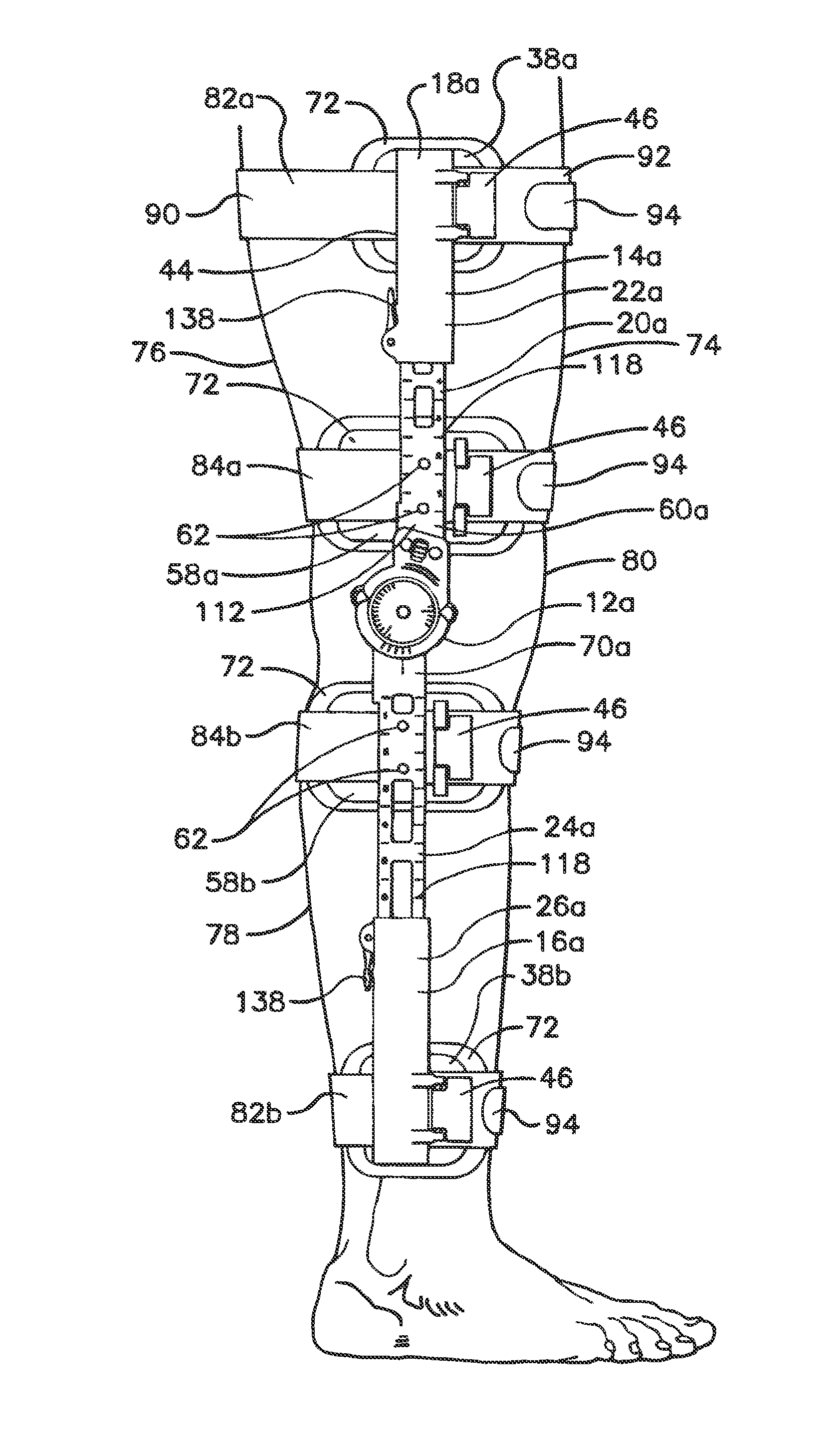
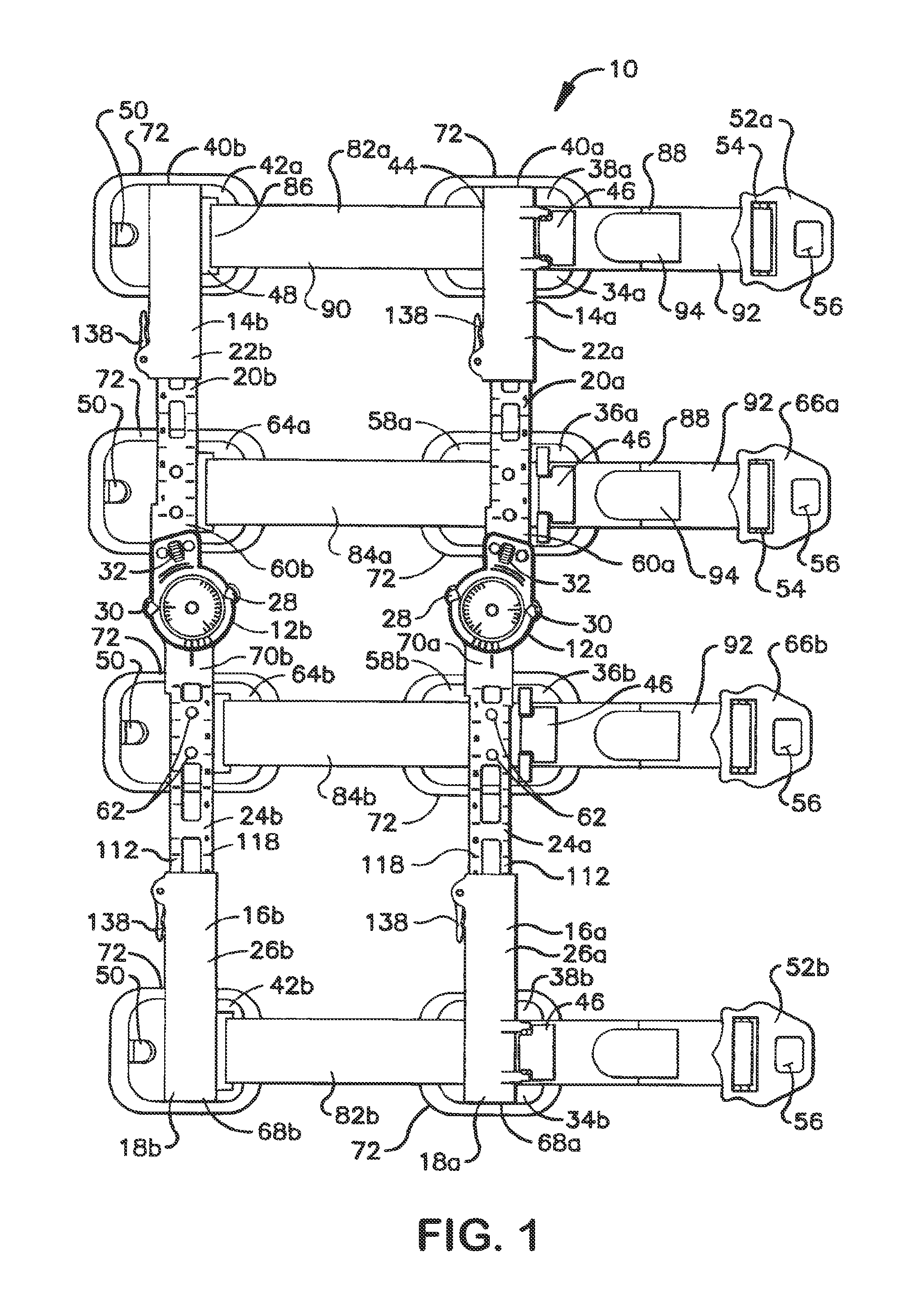
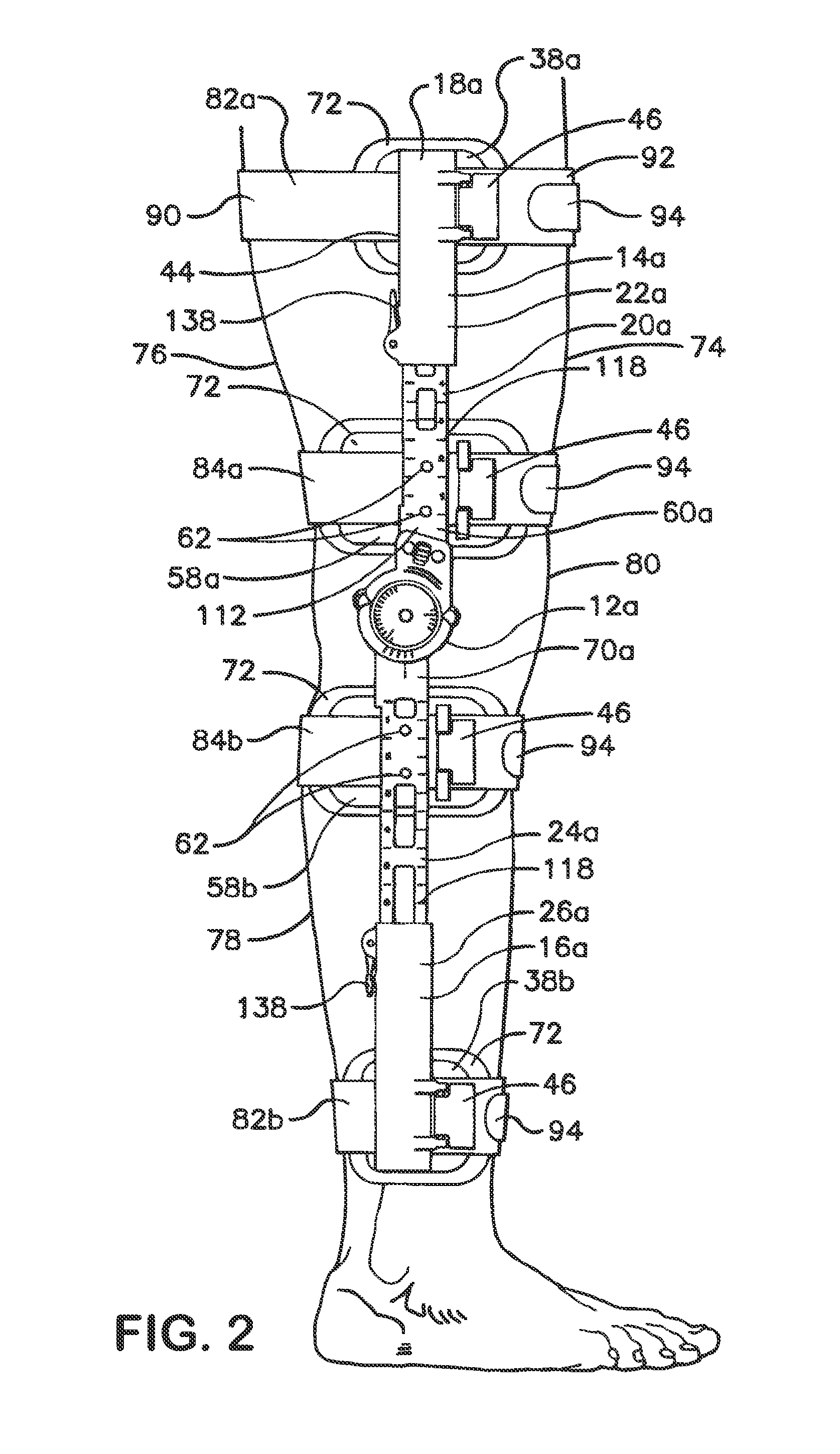
[0063]Referring initially to FIG. 1, an orthopedic brace is shown and generally designated 10. There are a number of relative terms defined below which are used in the following description to distinguish various elements of the orthopedic brace 10 from one another, but which are not to be construed as limiting the scope of the invention. The relative terms “medial” and “lateral” characterize certain elements of the orthopedic brace 10 and, in particular, describe the relative proximity of the given element to the central longitudinal axis of the body of the user when the brace 10 is mounted thereon. A “medial” element is closer to the central longitudinal axis of the body, while a “lateral” element is further from the central longitudinal axis of the body.

[0064]The terms “proximal” and “distal” characterize certain elements of the brace 10, which are aligned with the longitudinal axis of the brace 10. The terms describe the relative proximity of the given element to the central joi...


PUM


Abstract

An orthopedic brace is provided with an adjustable support assembly having a support arm, a housing and a locking mechanism. The housing includes a travel track which slidably receives the support arm. The locking mechanism includes a lock lever which selectively applies a sufficient force to the support arm to prevent slidable displacement of the support arm in the travel track. The orthopedic brace is further provided with a hinge having a first rotation plate, a second rotation plate, a pivotal connector connecting the first and second rotation plates, a rotation limiting mechanism, and a rotation locking mechanism.

Description

[0001]This application is a continuation of prior application Ser. No. 11 / 039,056 filed on Jan. 12, 2005.TECHNICAL FIELD[0002]The present invention relates generally to orthopedic braces, and more particularly to an orthopedic brace having a length-adjusting mechanism and a lockable rotation hinge.BACKGROUND OF THE INVENTION[0003]Orthopedic braces are worn on the body of a user either to support a healthy skeletal joint that is at risk of injury or to stabilize a skeletal joint that has been destabilized by an injury or other condition. Orthopedic braces generally include rigid structural components to support or stabilize the skeletal joint. Frequently, although not necessarily, the rigid structural components are dynamically linked together by one or more hinges enabling controlled pivotal movement of the skeletal joint during user activity or rehabilitative therapy. The orthopedic brace is positioned on the body such that the hinges traverse the skeletal joint, while the rigid co...

Claims


Application Information

Patent Timeline
IPC IPC(8): A61F5/00
CPCA61F5/0125A61F2005/0167A61F2005/0158A61F2005/0139
Inventor ODDOU, PAULCERIANI, DYLANN D.BURKE, JAMES D.MASON, JEFFREY T.
Owner BREG
Learn More