
Circulation control valve and associated method

a technology of control valve and valve body, applied in the direction of fluid removal, sealing/packing, borehole/well accessories, etc., can solve the problem of not being completely satisfactory in the performance of the valve body

Active Publication Date: 2011-04-07
HALLIBURTON ENERGY SERVICES INC
View PDF45 Cites 9 Cited by
  • Summary
  • Abstract
  • Description
  • Claims
  • Application Information

AI Technical Summary

Benefits of technology

In one aspect, a circulation control valve for use in a subterranean well is provided. The valve includes at least one opening for providing fluid communication between an interior longitudinal flow passage and an exterior of the valve. The valve also includes first and second valve devices. Fluid communication is provided through each of the first and second valve devices in response to application of a respective one of first and second pressure differentials applied across the corresponding valve device. Fluid communication through the opening is permitted in response to application of the first pressure differential to the first valve device, and fluid communication through the opening is prevented in response to application of the second pressure differential to the second valve device.
In another aspect, a circulation control valve is provided which includes at least one opening for providing fluid communication between an exterior of the valve and an interior longitudinal flow passage extending through the valve, a generally tubular closure device circumscribing the interior flow passage, and an internal chamber for containing pressurized fluid. The closure device displaces in a first direction in response to application of a first pressure differential between the interior flow passage and the internal chamber to thereby permit fluid communication through the opening. The closure device displaces in a second direction opposite to the first direction in response to release of a second pressure differential between the interior flow passage and the internal chamber to thereby prevent fluid communication through the opening.
In yet another aspect, a method of controlling circulation flow between an interior flow passage of a tubular string and an annulus external to the tubular string in a subterranean well is provided. The method includes the steps of: interconnecting a valve in the tubular string, the valve including at least one opening for providing fluid communication between the interior flow passage and the annulus; applying an increased pressure to the interior flow passage while fluid communication through the opening between the interior flow passage and the annulus is prevented, thereby permitting fluid communication through the opening between the interior flow passage and the annulus; and then applying another increased pressure to the interior flow passage while fluid communication through the opening between the interior flow passage and the annulus is permitted, thereby preventing fluid communication through the opening between the interior flow passage and the annulus.

Problems solved by technology

Although circulation control valves for these purposes have been used in the past, they have not been entirely satisfactory in their performance.

Method used


Image

  • Circulation control valve and associated method
  • Circulation control valve and associated method
  • Circulation control valve and associated method

Examples


Embodiment Construction

It is to be understood that the various embodiments of the present invention described herein may be utilized in various orientations, such as inclined, inverted, horizontal, vertical, etc., and in various configurations, without departing from the principles of the present invention. The embodiments are described merely as examples of useful applications of the principles of the invention, which is not limited to any specific details of these embodiments.

In the following description of the representative embodiments of the invention, directional terms, such as “above”, “below”, “upper”, “lower”, etc., are used for convenience in referring to the accompanying drawings. In general, “above”, “upper”, “upward” and similar terms refer to a direction toward the earth's surface along a wellbore, and “below”, “lower”, “downward” and similar terms refer to a direction away from the earth's surface along the wellbore.

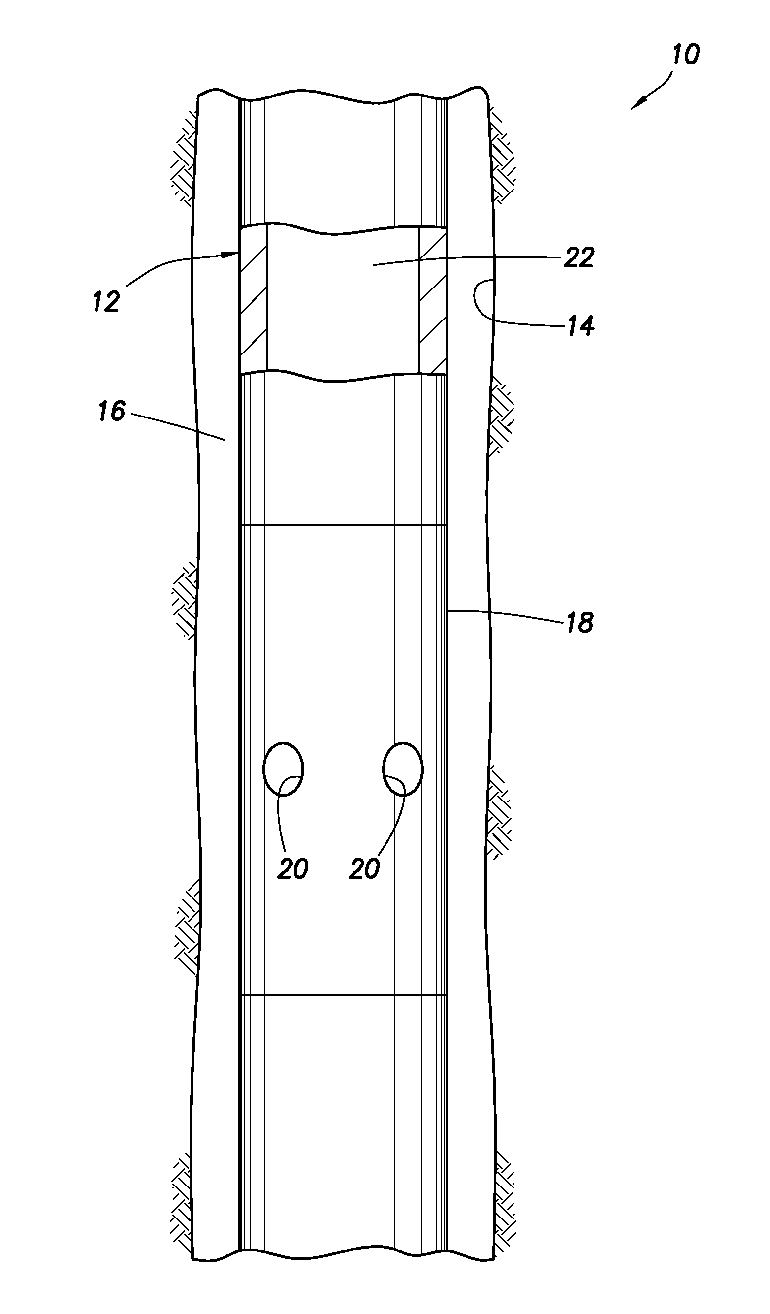
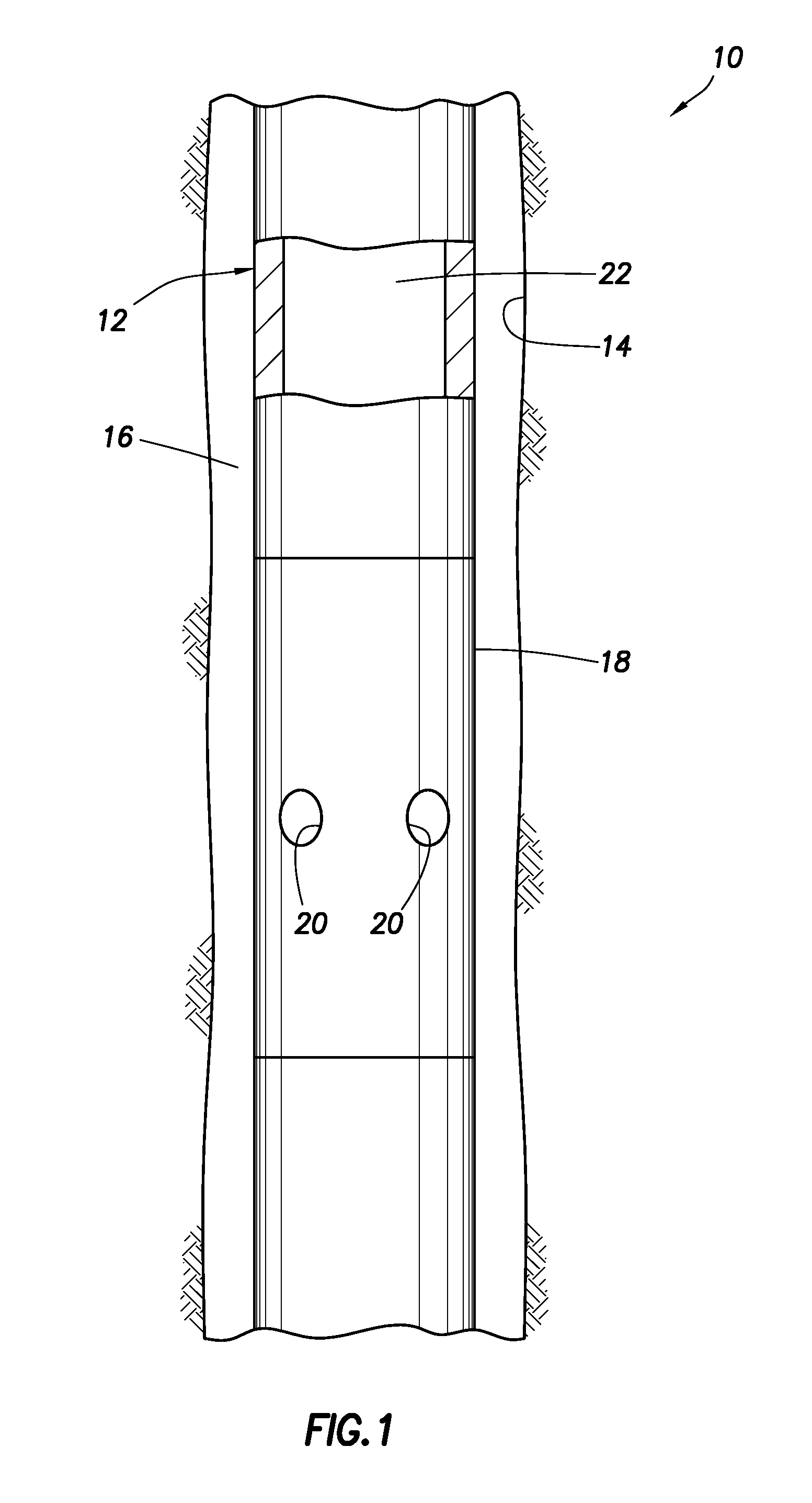
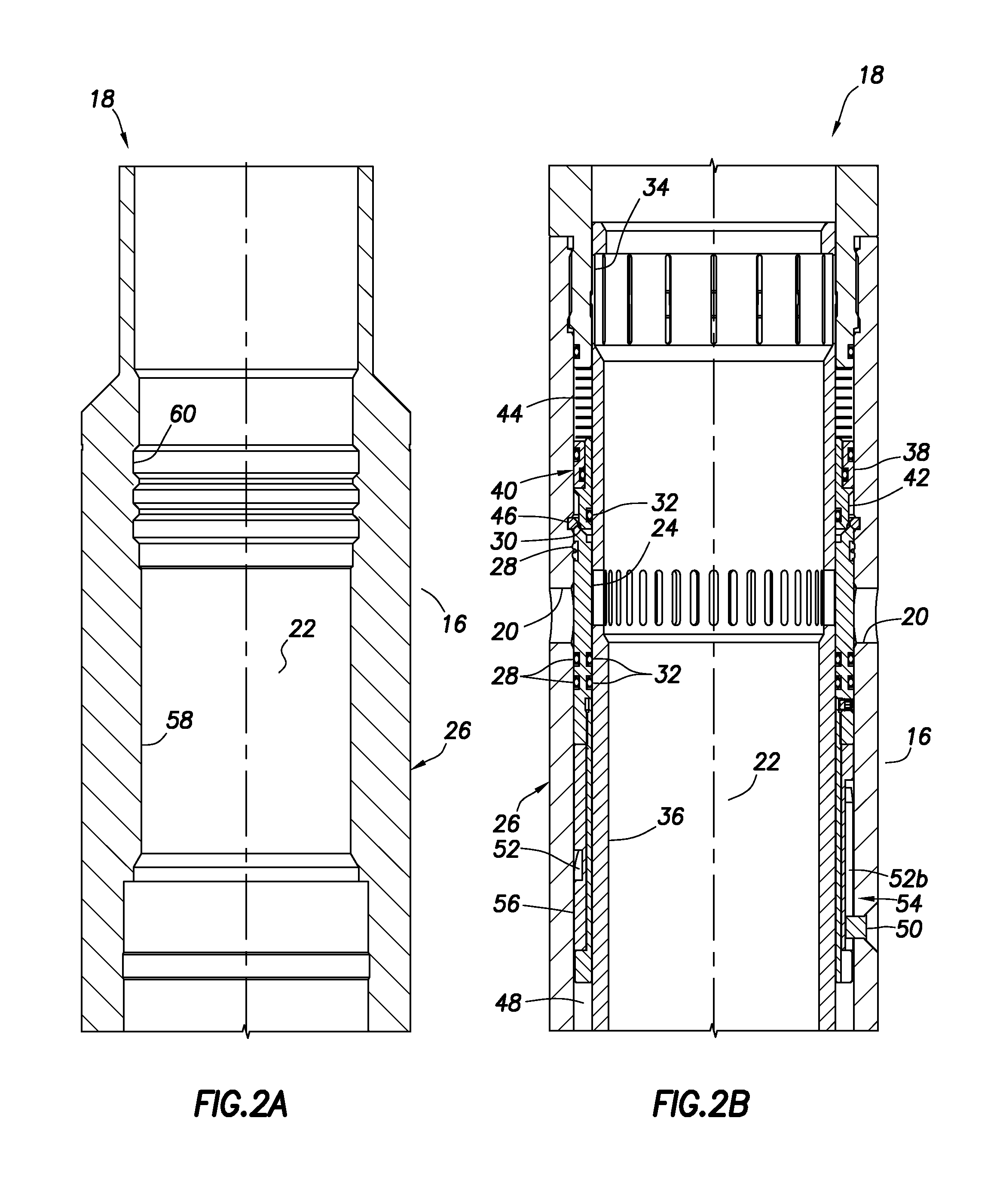
Representatively illustrated in FIG. 1 is a well system and associated meth...


PUM


Abstract

A circulation control valve. A method of controlling circulation flow between an interior flow passage of a tubular string and an annulus external to the tubular string in a subterranean well includes the steps of: interconnecting a valve in the tubular string, the valve including at least one opening for providing fluid communication between the interior flow passage and the annulus; applying an increased pressure to the interior flow passage while fluid communication through the opening between the interior flow passage and the annulus is prevented, thereby permitting fluid communication through the opening between the interior flow passage and the annulus; and then applying another increased pressure to the interior flow passage while fluid communication through the opening between the interior flow passage and the annulus is permitted, thereby preventing fluid communication through the opening between the interior flow passage and the annulus.

Description

BACKGROUNDThe present invention relates generally to equipment utilized and operations performed in conjunction with a subterranean well and, in an embodiment described herein, more particularly provides a circulation control valve and associated method.It is frequently beneficial to be able to selectively permit and prevent circulation flow through a sidewall of a tubular string in a well. For example, at the conclusion of a cementing operation, in which the tubular string has been cemented in the well, it is sometimes desirable to circulate cement out of a portion of an annulus exterior to the tubular string. As another example, in staged cementing operations it may be desirable to flow cement through sidewall openings in a tubular string. Numerous other examples exist, as well.Although circulation control valves for these purposes have been used in the past, they have not been entirely satisfactory in their performance. For example, one circulation control valve includes multiple...

Claims


Application Information

Patent Timeline
Patent Type & Authority Applications(United States)
IPC IPC(8): E21B34/08
CPCE21B21/103E21B34/10E21B23/006
Inventor WILLIAMSON, JR., JIMMIE R.
Owner HALLIBURTON ENERGY SERVICES INC
Learn More