
Temperature estimation apparatus for aeroplane gas turbine engine

a technology of temperature estimation apparatus and gas turbine engine, which is applied in the direction of heat measurement, instruments, analogue processes for specific applications, etc., can solve the problem that the inlet temperature of high-pressure turbines cannot be estimated based on the inlet temperature, and achieve accurate estimation of the inlet temperature

Active Publication Date: 2011-03-31
HONDA MOTOR CO LTD
View PDF2 Cites 29 Cited by
  • Summary
  • Abstract
  • Description
  • Claims
  • Application Information

AI Technical Summary

Benefits of technology

The patent text describes a temperature estimation apparatus for an aeroplane gas turbine engine. The apparatus includes sensors to detect the rotational speed of the high-pressure turbine and the low-pressure turbine, as well as an estimator to estimate the inlet temperature of the high-pressure turbine based on the detected outlet temperature of the low-pressure turbine and its rotational speed. A corrector is also included to correct the estimated inlet temperature of the high-pressure turbine with the detected rotational speed of the high-pressure turbine. The technical effect of this invention is to accurately estimate the inlet temperature of the high-pressure turbine based on the outlet temperature of the low-pressure turbine.

Problems solved by technology

However, since the inlet temperature is extremely high so that it is impossible to directly detect it, it is configured to detect inlet temperature of the low-pressure turbine downstream of the high-pressure turbine and based thereon, estimate the inlet temperature of the high-pressure turbine.
However, since it is difficult to keep a space for a temperature sensor at or in the vicinity of the inlet of the low-pressure turbine of the aeroplane gas turbine engine which is required to be compact, the inlet temperature of the high-pressure turbine can not be estimated based on the inlet temperature of the low-pressure turbine.

Method used


Image

  • Temperature estimation apparatus for aeroplane gas turbine engine
  • Temperature estimation apparatus for aeroplane gas turbine engine
  • Temperature estimation apparatus for aeroplane gas turbine engine

Examples


Embodiment Construction

[0017]A temperature estimation apparatus for an aeroplane gas turbine engine according to a preferred embodiment of the present invention will now be explained with reference to the attached drawings.

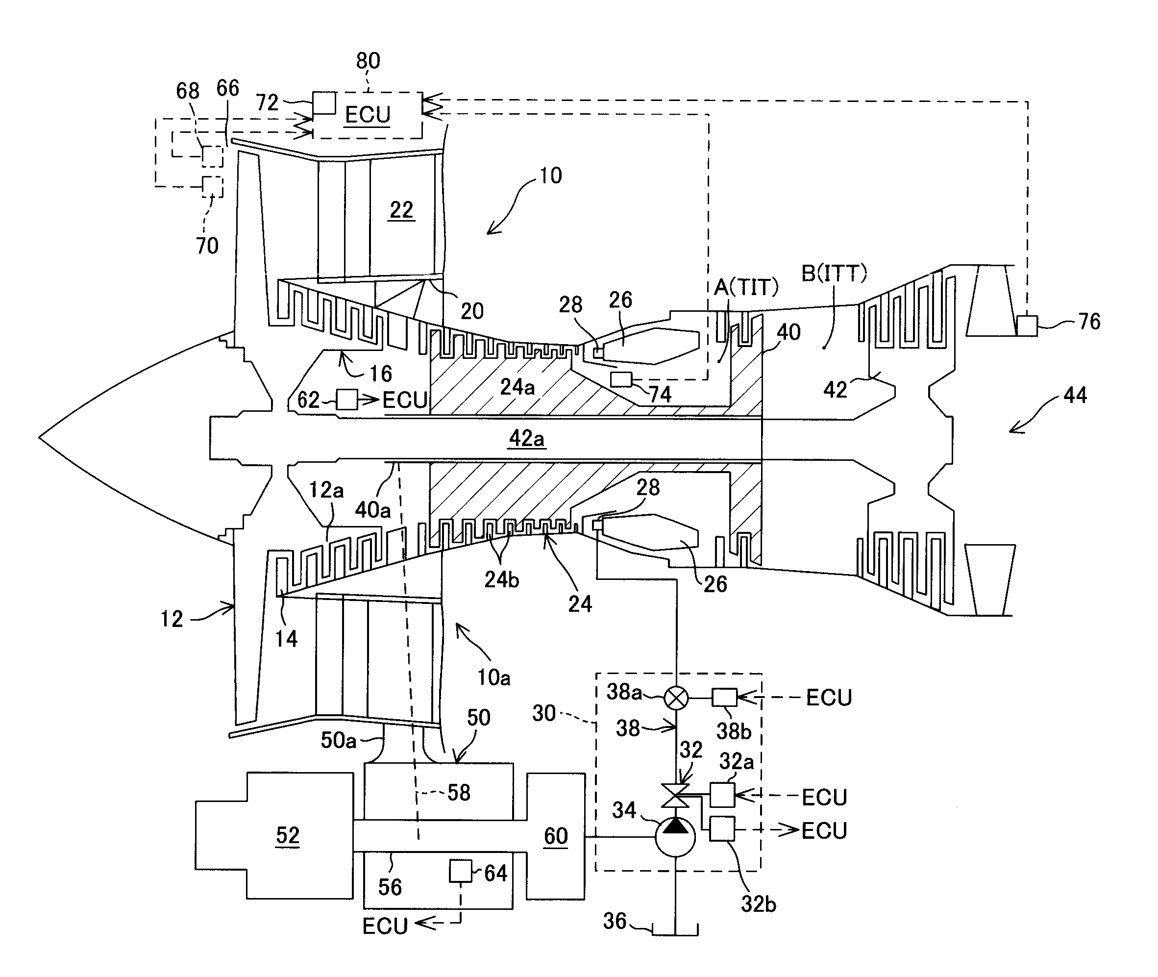
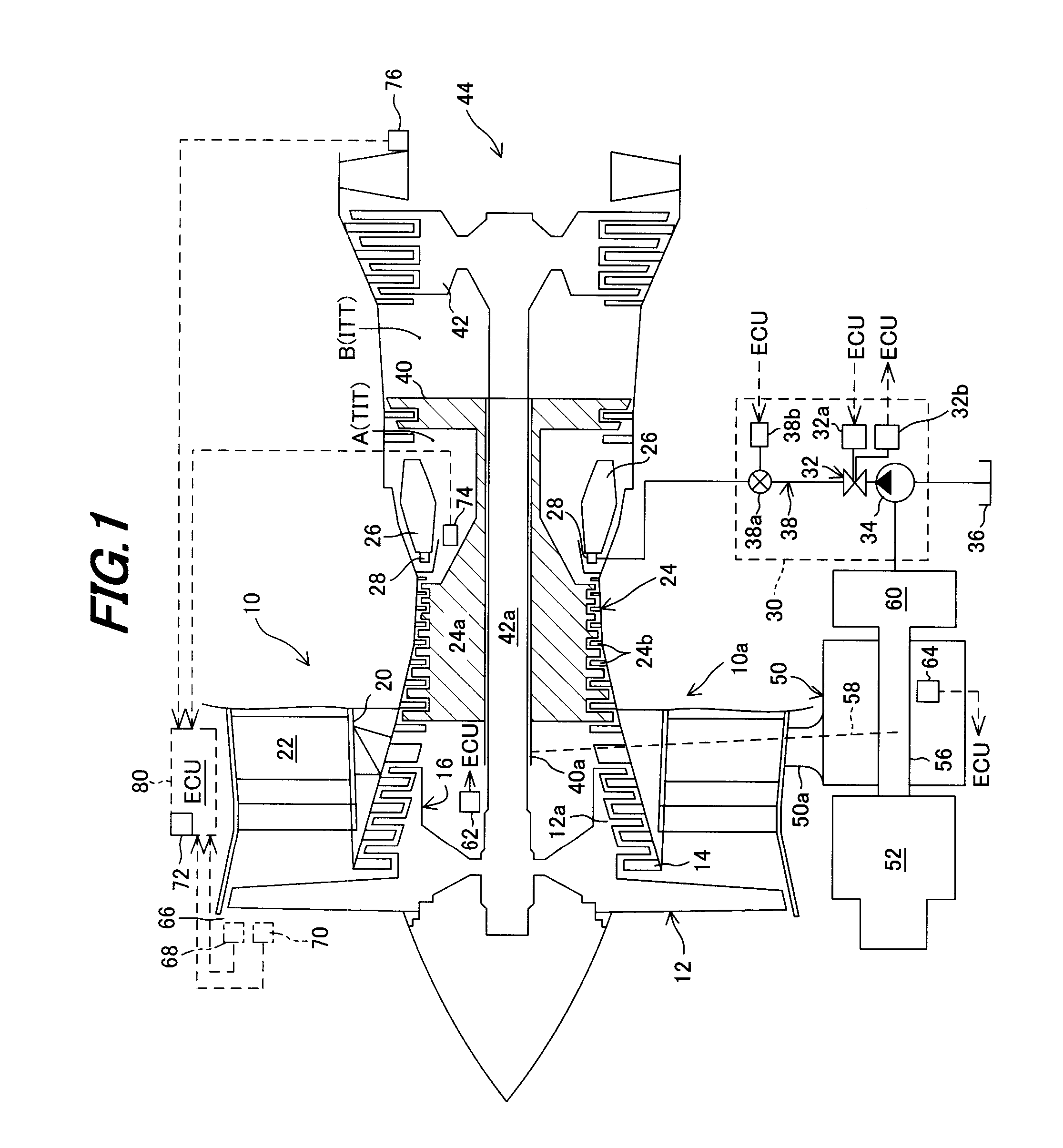
[0018]FIG. 1 is an overall schematic view of a temperature estimation apparatus for an aeroplane gas turbine engine according to an embodiment of this invention.

[0019]Four types of gas turbine engines, i.e., aeroplane gas turbine engines are commonly known: the turbojet engine, turbofan engine, turboprop engine and turboshaft engine. A two-shaft turbofan engine will be taken as an example in the following explanation.

[0020]In FIG. 1, reference numeral 10 designates a turbofan engine (gas turbine engine; hereinafter referred to as “engine”). Reference numeral 10a designates a main engine unit. The engine 10 is mounted at an appropriate location of an aircraft (airframe; not shown).

[0021]The engine 10 is equipped with a fan (fan blades) 12 that sucks in air while rotating rapidly. A rotor...


PUM

PropertyMeasurementUnit
altitudeaaaaaaaaaa
temperatureaaaaaaaaaa
pressureaaaaaaaaaa

Abstract

In a temperature estimation apparatus for an aeroplane gas turbine engine mounted on an aircraft and having a combustion chamber, a high-pressure turbine rotated by combustion gas exhausted from the combustion chamber, a low-pressure turbine located downstream of the high-pressure turbine to be rotated by low-pressure gas which has passed through the high-pressure turbine, a high-pressure turbine rotational speed sensor, a low-pressure turbine rotational speed sensor, and a temperature sensor, inlet temperature at an inlet of the high-pressure turbine is estimated based on the detected outlet temperature of the low-pressure turbine and the rotational speed of the low-pressure turbine and is corrected with the detected rotational speed of the high-pressure turbine.

Description

BACKGROUND OF THE INVENTION[0001]1. Field of the Invention[0002]This invention relates to a temperature estimation apparatus for an aeroplane gas turbine engine.[0003]2. Description of the Related Art[0004]In an aeroplane gas turbine engine equipped with a high-pressure turbine rotated by high-pressure gas injected from a combustion chamber of the engine and with a low-pressure turbine located downstream of the high-pressure turbine and rotated by low-pressure gas passed therethrough, it is preferable to detect the temperature at an inlet of the high-pressure turbine for preventing the overheat of the engine. However, since the inlet temperature is extremely high so that it is impossible to directly detect it, it is configured to detect inlet temperature of the low-pressure turbine downstream of the high-pressure turbine and based thereon, estimate the inlet temperature of the high-pressure turbine.[0005]However, since it is difficult to keep a space for a temperature sensor at or i...

Claims


Application Information

Patent Timeline
Patent Type & Authority Applications(United States)
IPC IPC(8): G01K11/00G01K1/16
CPCG01K7/42G01K2205/02G01K13/02
Inventor MURAMATSU, HIRONORISAITA, TOMOHISA
Owner HONDA MOTOR CO LTD
Learn More