
Geothermal system and tubing therefor

Inactive Publication Date: 2011-03-31
IPL
View PDF7 Cites 0 Cited by
  • Summary
  • Abstract
  • Description
  • Claims
  • Application Information

AI Technical Summary

Benefits of technology

[0008]A system is provided having a pump. The pump is operatively coupled to a tubing having made of a high thermally conductive material. The tubing is adapted to promote the transfer of energy between a fluid contained therein and earth surrounding the pipe.
[0009]In one embodiment, the tubing is made from a high density polyethyle

Problems solved by technology

These systems, although rudimentary have been satisfactory, but fairly inefficient.
First, the materials used have a low thermal conductivity, so that the necessary heat exchange between the ground and the fluid is difficult, requiring a longer run of tubing within the ground to maximize energy transfer.
Furthermore, energy is wasted because the thermal conductivity is not sufficiently high to maintain the temperature of the fluid for long stretches of travel through the ground.

Method used


Image

  • Geothermal system and tubing therefor
  • Geothermal system and tubing therefor

Examples


Embodiment Construction

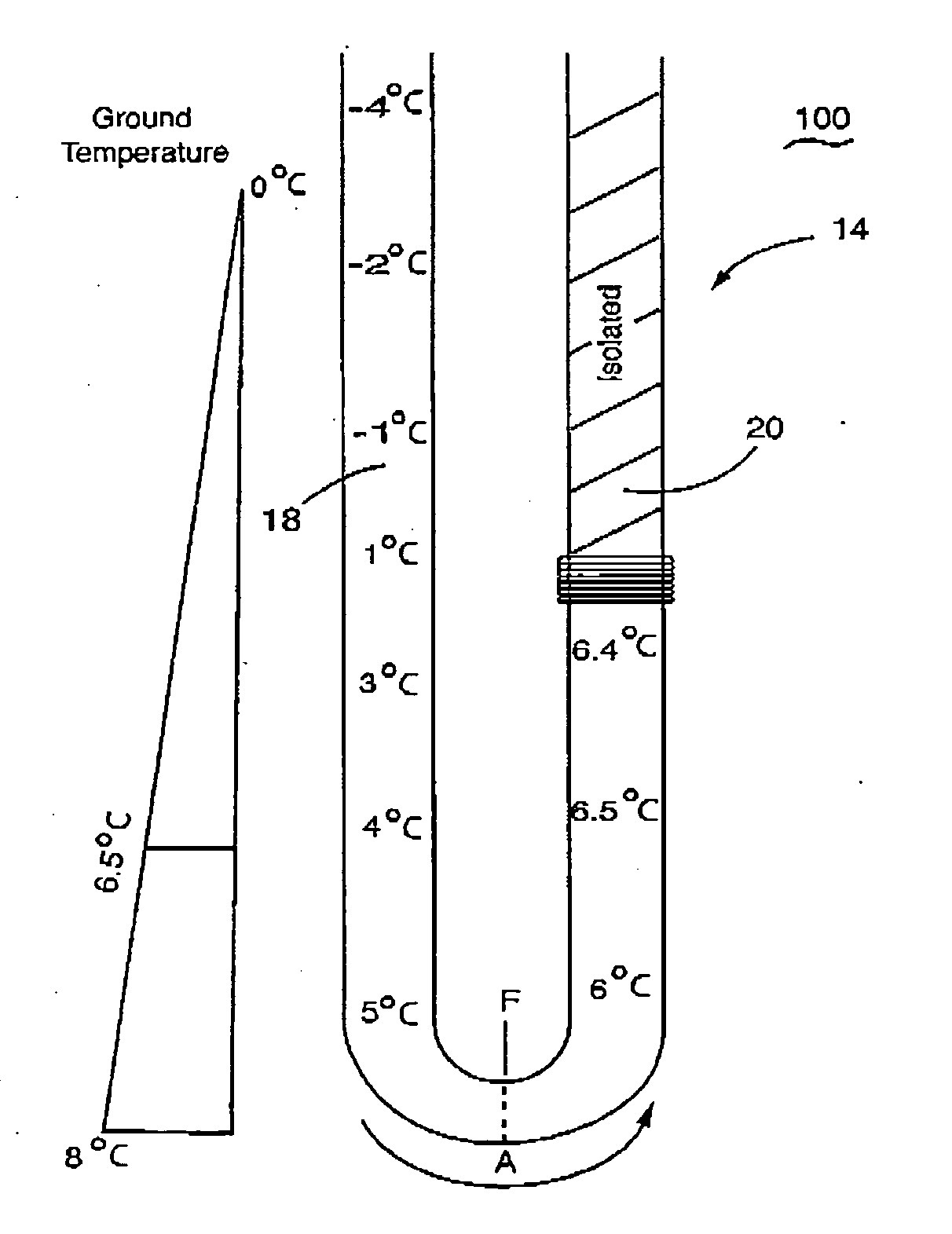
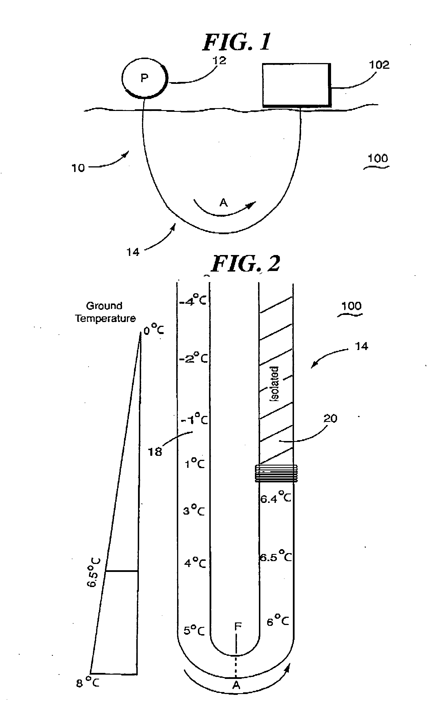
[0013]Reference is made to the FIGS. 1 and 2 in which a geothermal heat pump, generally indicated as 10, is provided. Heat pump 10 includes a pump 12 for pumping a fluid. A pipe, generally indicated as 14 conveys the fluid from pump 12 in the direction of Arrow A. At least a portion of the path of pipe 14 is through ground 100 near the facility (a house, building or the like) 102 to be controlled by heat pump 10. In a preferred embodiment, pipe 14 is a plastic tubing.

[0014]In one embodiment of the invention, pipe tubing 14 is formed of a high density polyethylene (above 0.940 g / cm3) having a high thermal conductivity, preferably about 0.5 W / (m−K) or higher, and preferably, about 0.7 W / (m−K) or higher.

[0015]At the depths through ground 20 through which tubing 14 will travel, the temperature of the earth reaches about 8° C. The desired temperature of the fluid approximates that of the temperature of the ground at the depth to which the tubing 14 travels.

[0016]The temperature of the gr...


PUM


Abstract

A geothermal heat pump has a pump. A tubing conveys a fluid from the pump and adapted to transfer energy between the fluid and the ambient environment as the fluid travels through the tubing. The tubing has a high thermal conductivity.

Description

CROSS-REFERENCE TO RELATED APPLICATION[0001]This application claims priority to U.S. Provisional Application No. 61 / 226,561 filed on Jul. 17, 2009 in its entirety.BACKGROUND OF THE INVENTION[0002]This invention is directed to a geothermal system, and more particularly to the fluid transfer structure therefor.[0003]Geothermal energy systems are known in the art. By way of example a geothermal heat pump utilizes the ground temperature to heat or cool a fluid through energy transfer with the ground to regulate the interior temperature of a facility. The system uses the earth as either a source of heat in the winter or as a coolant in the summer. The geothermal heat pumps take advantage of substantially consistent moderate temperatures in the shallow ground to boost efficiency and reduce operational cost. The temperature of the ground remains fairly constant except for very close to the surface while the temperature of the air above ground, and within a facility, changes relatively dram...

Claims


Application Information

Patent Timeline
IPC IPC(8): F24J3/08
CPCY02E10/12F24J3/081F24T10/10Y02E10/10
Inventor LEGER, ALEXANDREMAGNI, ERIC
Owner IPL
Learn More