
Windshield wiper drive and motor vehicle having a windshield wiper drive

a technology of windshield wipers and wiper drives, which is applied in the direction of vehicle maintenance, vehicle cleaning, cleaning equipment, etc., can solve the problems of premature wear of sealing elements, increased leakage over service life, and so as to minimize the danger of water penetration into the interior of the housing

Inactive Publication Date: 2011-03-31
ROBERT BOSCH GMBH
View PDF5 Cites 3 Cited by
  • Summary
  • Abstract
  • Description
  • Claims
  • Application Information

AI Technical Summary

Benefits of technology

The invention proposes a windshield wiper drive with a protective cap that minimizes the risk of water entering the housing. The protective cap is made of an elastic material, such as rubber, and is designed to seal directly with the wiper shaft or other components of the windshield wiper drive. This sealing effect prevents water from reaching the interior of the housing and avoids the need for additional annular seals. The protective cap can be held in place using a fastening component, such as a sheet metal bent part, and can be designed to engage with the contact disk or the vehicle body. The technical effect of this invention is to provide a windshield wiper drive with a protective cap that optimizes sealing and prevents water from entering the housing, leading to increased service life of the windshield wiper drive.

Problems solved by technology

A disadvantage of both variants is that water, in particular saline and contaminated water, can penetrate the region enclosed by the protective cap through swirl and therefore, after spending a certain time on the annular seal, will necessarily advance into the interior of the housing.
Especially in the case of a fixed protective cap, the latter is unavoidably subjected to wear at the interface with the wiper shaft, necessarily leading to additional leaks over the service life thereof.
At that time at the latest, the water which has entered cannot drain, or drain completely, and can therefore advance to the annular sealing element between the wiper shaft and the internal circumference of the output dome, leading to premature wear of the sealing element, and consequently to penetration of water into the interior of the housing.

Method used


Image

  • Windshield wiper drive and motor vehicle having a windshield wiper drive
  • Windshield wiper drive and motor vehicle having a windshield wiper drive
  • Windshield wiper drive and motor vehicle having a windshield wiper drive

Examples


Embodiment Construction

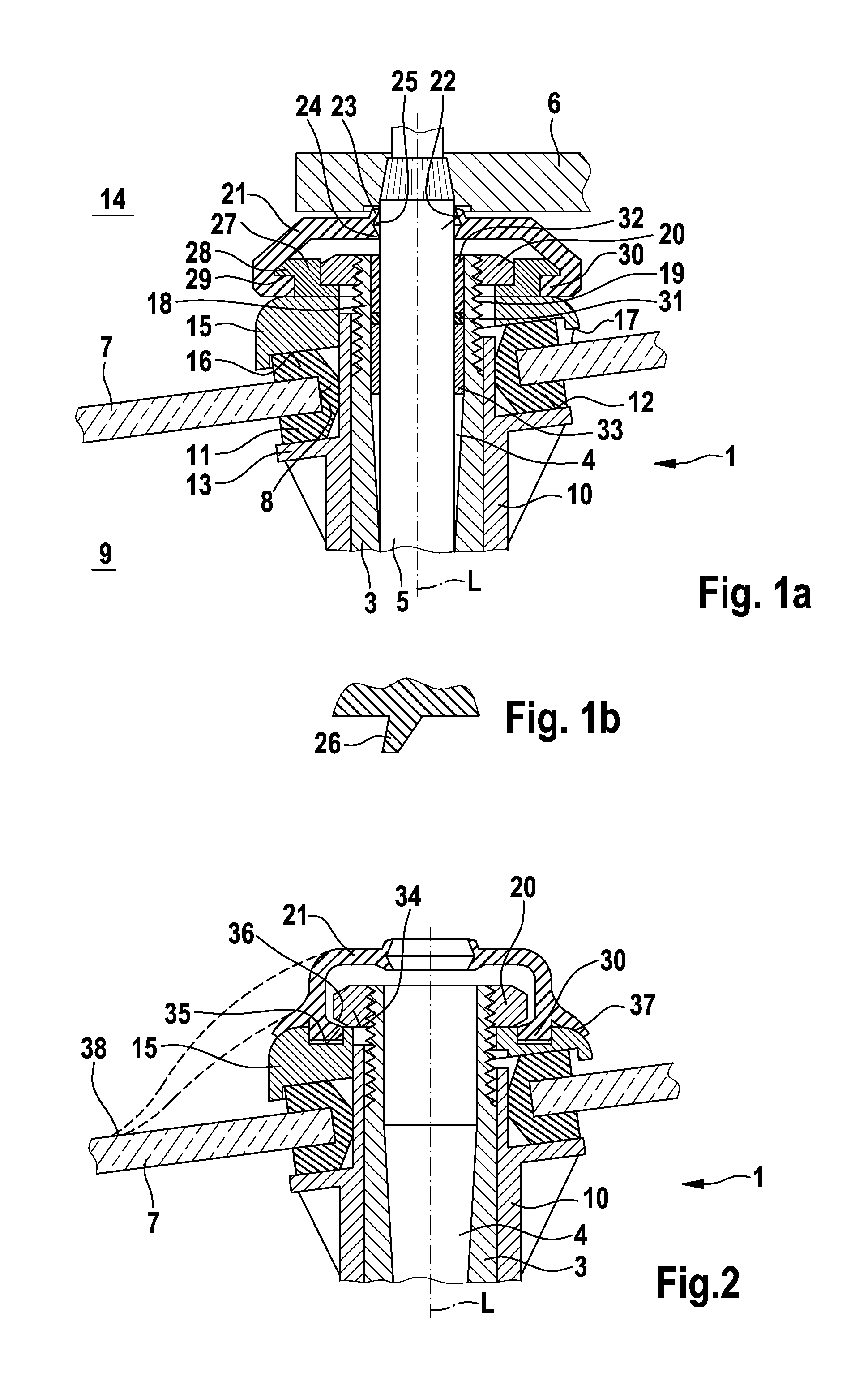
[0020]In the figures identical components and components having the same function are denoted by the same reference numerals.

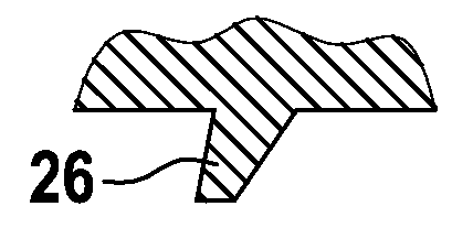
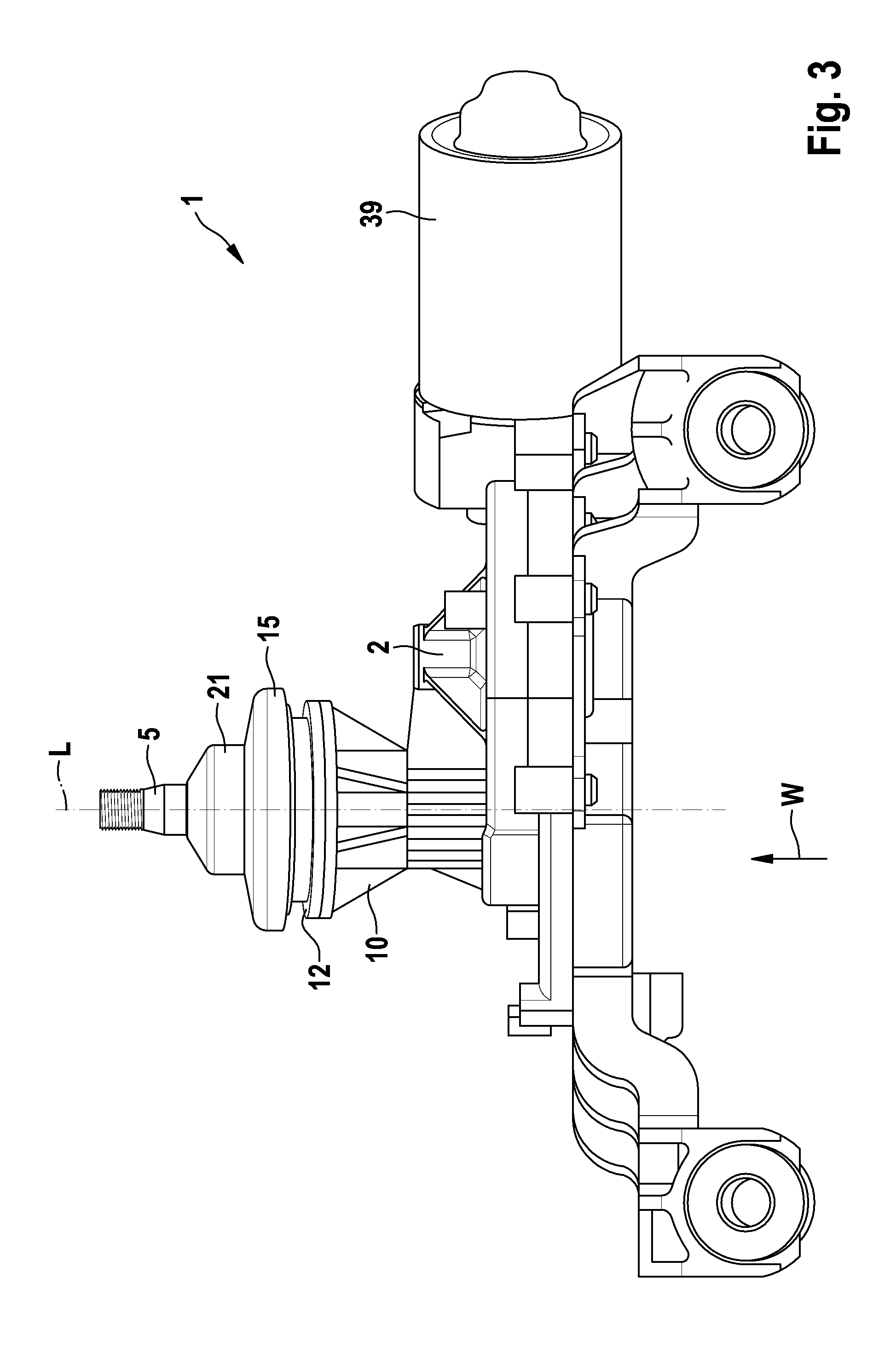
[0021]FIG. 1a shows a section of a windshield wiper drive 1 in the form of a rear window wiper drive. The windshield wiper drive 1 may be embodied as shown in FIG. 3. It comprises a housing 2 with an integrally formed output dome 3 which has a central through-opening 4. A transmission, preferably in the form of a worm gear, is accommodated in known fashion within the housing 2, only the output dome 3 of which is represented in FIG. 1, which transmission is driven by an electric motor. A wiper shaft 5, which passes through the through-opening 4 of the output dome 3 in the axial direction, is driven in an oscillatory fashion about its longitudinal central axis L by means of the drive motor (not shown) and the transmission (also not shown).

[0022]A wiper arm 6, which moves across a rear window 7 when the wiper shaft 5 is driven oscillatingly, is fastened non-rotat...


PUM


Abstract

The invention relates to a windshield wiper drive (1), particularly a motor vehicle rear window wiper drive, comprising a housing (2) having an output dome (3) penetrated by a wiper shaft (5) and penetrating a contact disk (15), said dome having an external thread (19) in the region of the free end (18) thereof, onto which a nut (20) is screwed for tightening the contact disk (15), the nut being disposed inside a protective cap (21) penetrated by the wiper shaft (15). The invention provides that the protective cap (21) comprises an elastomer material. The invention further relates to a motor vehicle.

Description

BACKGROUND OF THE INVENTION[0001]The invention relates to a windshield wiper drive, in particular a motor vehicle rear window wiper drive, and to a motor vehicle with a windshield wiper drive.[0002]In known rear window wiper drives, the transmission housing usually has an output dome which penetrates a rear window or the vehicle body, the output dome in turn being penetrated by the wiper shaft. In order to fasten the windshield wiper drive to the rear window or to the vehicle body, there is provided at an end of the output dome an external thread which serves to receive a nut by tightening which the transmission housing can be fastened to the rear window or to the vehicle body. The seal between the wiper shaft and the opening in the output dome is effected by means of an annular seal which is received in a region located radially between the wiper shaft and the internal circumference of the output dome. In order to protect the wiper shaft exit region additionally against direct expo...

Claims


Application Information

Patent Timeline
Patent Type & Authority Applications(United States)
IPC IPC(8): B60S1/06B60S1/58
CPCB60S1/0436B60S1/0444B60S1/583B60S1/3493B60S1/349
Inventor BOHN, ROLANDHUESGES, MARIOSTERNS, ORLANDO
Owner ROBERT BOSCH GMBH
Learn More