Indexing drive system

a drive system and indexing technology, applied in the direction of gearing, couplings, hoisting equipment, etc., can solve the problems of one or more components of the tenderizer drive likely to break, complex systems with critical timing problems, rod end problems

Inactive Publication Date: 2011-03-24
ROSS IND
View PDF17 Cites 4 Cited by
  • Summary
  • Abstract
  • Description
  • Claims
  • Application Information

AI Technical Summary

Problems solved by technology

These are complex systems with critical timing issues.
These systems do not typically include overload protection, so if a jam should occur in the tenderizer, one or more components of the tenderizer drive are likely to break, often a rod end or a linkage arm.

Method used


Image

  • Indexing drive system
  • Indexing drive system
  • Indexing drive system

Examples


Embodiment Construction

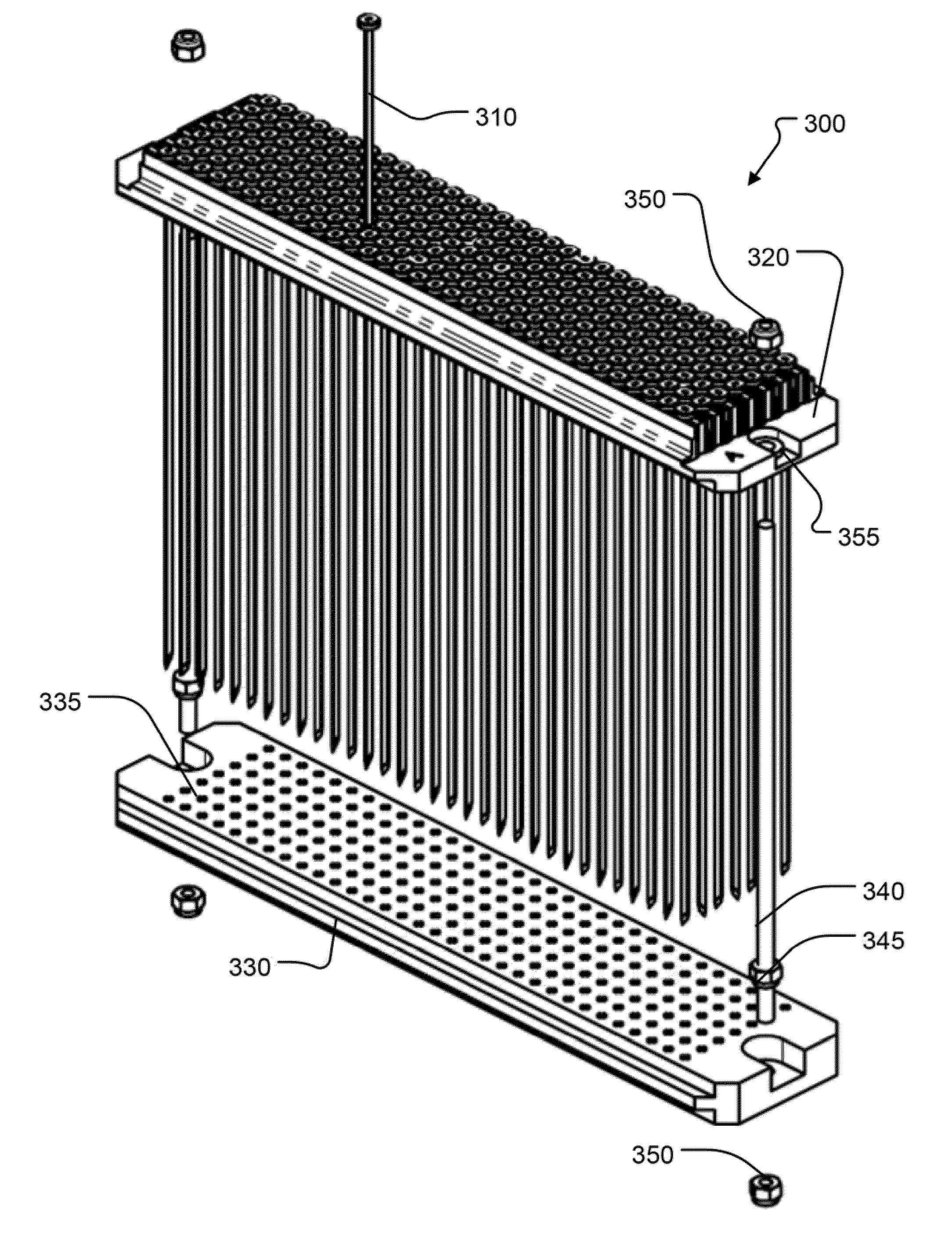
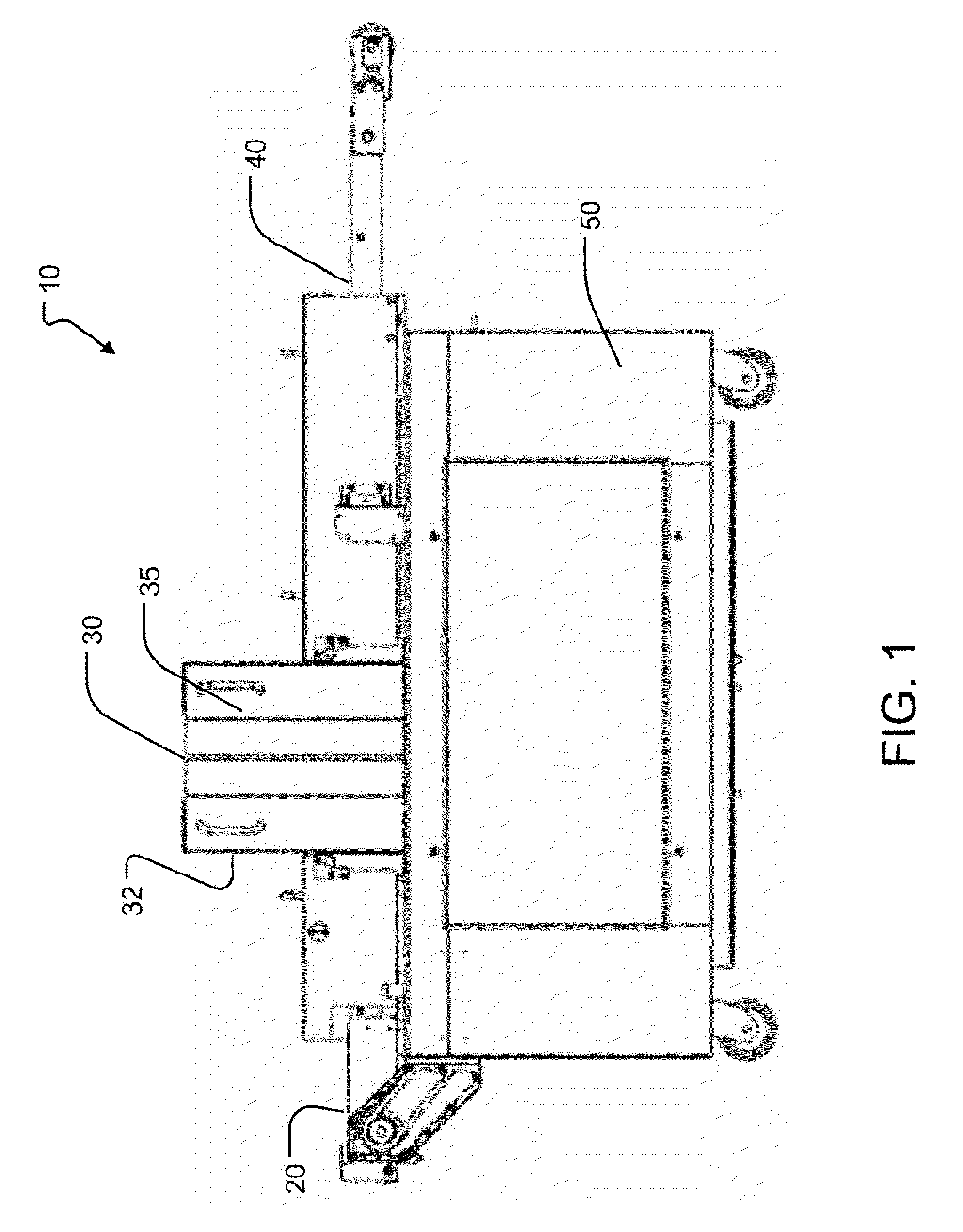
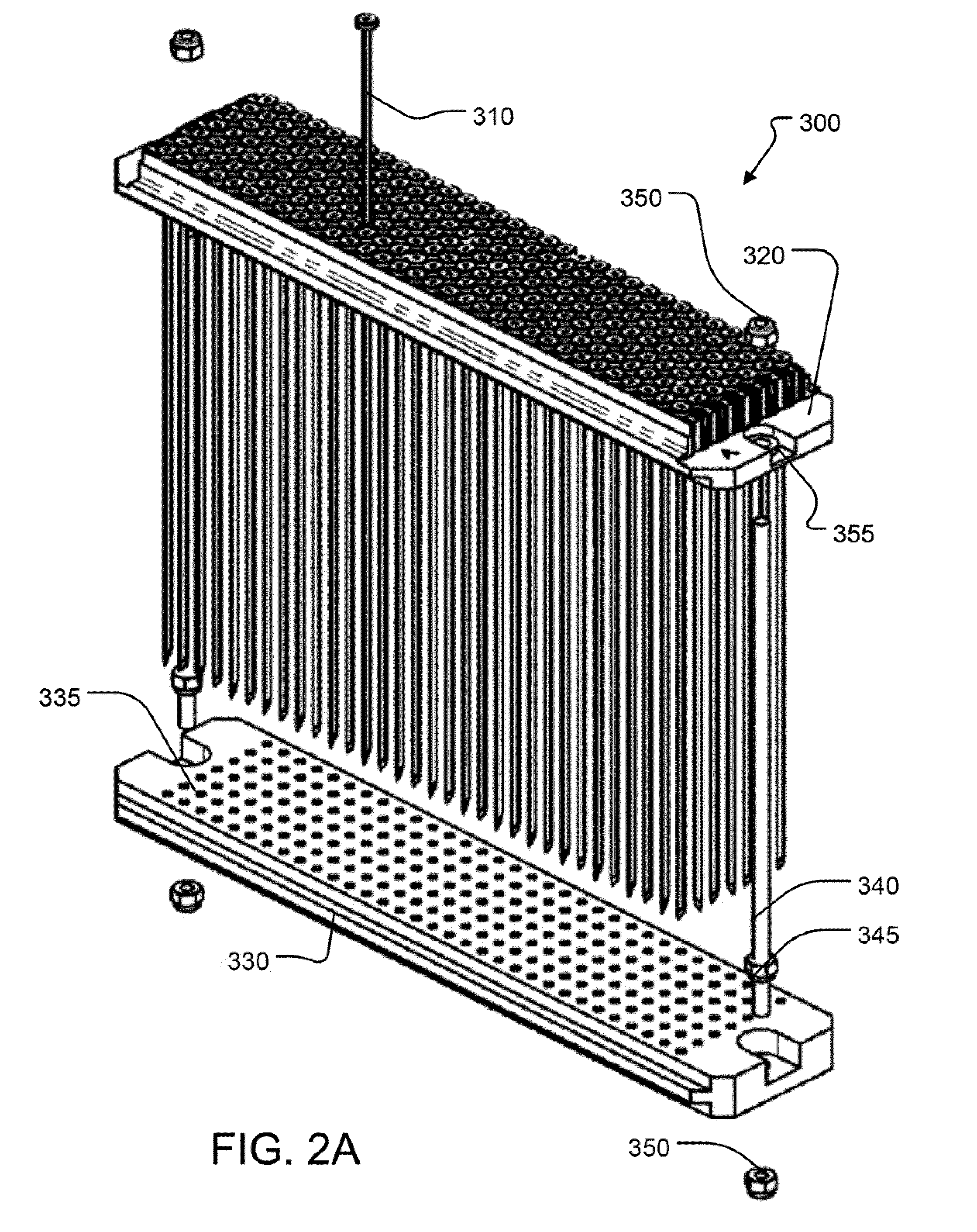
[0032]The embodiments of the disclosure and the various features and advantageous details thereof are explained more fully with reference to the non-limiting embodiments and examples that are described and / or illustrated in the accompanying drawings, and detailed in the following attached description. It should be noted that the features illustrated in the drawings are not necessarily drawn to scale, and features of one embodiment may be employed with other embodiments as the skilled artisan would recognize, even if not explicitly stated herein. Descriptions of well-known components and processing techniques may be omitted so as to not unnecessarily obscure the embodiments of the disclosure. The examples used herein are intended merely to facilitate an understanding of ways in which the disclosure may be practiced and to further enable those of skill in the art to practice the embodiments of the disclosure. Accordingly, the examples and embodiments herein should not be construed as ...


PUM


Abstract

A driver for a food conditioner that comprises a drive shaft that is configured to be driven by a motor, a continuous-to-intermittent converter that is configured to be coupled to the drive shaft, and a slip clutch that is configured to be coupled to the continuous-to-intermittent converter, wherein the slip clutch is further configured to disengage when a torque applied to the slip clutch exceeds a predetermined threshold.

Description

CROSS REFERENCE TO PRIOR APPLICATIONS[0001]This application claims priority under 35 U.S.C. §119(e) to U.S. Provisional Patent Application No. 61 / 244,764, filed Sep. 22, 2009, and titled “Indexing Drive System for Tenderizer,” the disclosure of which is expressly incorporated by reference herein in its entirety.FIELD OF THE DISCLOSURE[0002]The present disclosure relates to an apparatus, a system and a method for driving a device for conditioning food products, such as, for example, meat, poultry, and the like, to improve their texture and improve consumer taste preference for the conditioned product when compared with an equivalent non-conditioned sample.BACKGROUND OF THE DISCLOSURE[0003]Mechanical blade tenderizers are commonly used by meat processors to cut through sinew and connective tissue when processing various cuts of meat and poultry. The process of cutting through sinew and connective tissue may increase the desirability of the resultant product, since consumers typically ...

Claims


Application Information

Patent Timeline
Patent Type & Authority Applications(United States)
IPC IPC(8): A22C9/00F16H55/17F16H57/02
CPCA22C9/008F16H27/06Y10T74/1987Y10T74/19642Y10T74/19879F16H35/10
Inventor SPILLNER, WAYNECLARKSON, LEECLOWATER, BILL
Owner ROSS IND
Why Eureka
Try Eureka