
Valve Timing Control Apparatus for Internal Combustion Engine, and Method of Producing Same

a timing control and internal combustion engine technology, applied in the direction of valve details, valve arrangements, valve drives, etc., can solve problems such as the deformation of the timing bel

Inactive Publication Date: 2011-03-17
HITACHI AUTOMOTIVE SYST LTD
View PDF13 Cites 32 Cited by
  • Summary
  • Abstract
  • Description
  • Claims
  • Application Information

AI Technical Summary

Benefits of technology

[0005]According to another aspect of the present invention, a valve timing control apparatus for an internal combustion engine, comprises: a housing body having a tubular shape including an opening at an axial end, wherein the housing body is formed integrally with a pulley at an outside periphery of the housing body, and wherein the pulley is adapted to receive torque from a crankshaft of the internal combustion engine; a sealing plate facing an axial end surface of the housing body, and closing the opening of the housing body; a phase change mechanism mounted in the housing body, and adapted to change a rotational phase of a camshaft of the internal combustion engine with respect to the housing body in response to supply and drainage of working fluid; and a sealing ring disposed between the housing body and the sealing plate, wherein: the housing body is formed of an aluminum-based metal material and anodized, wherein the housing body includes a base layer and an anodic oxide coating film layer; and the anodic oxide coating film layer is present at the outside periphery and an inside periphery of the housing body, and absent at the axial end surface of the housing body facing the sealing plate.
[0006]According to a further aspect of the present invention, a valve timing control apparatus for an internal combustion engine, comprises: a housing body having a tubular shape including an opening at an axial end, wherein the housing body is formed integrally with a pulley at an outside periphery of the housing body, and wherein the pulley is adapted to receive torque from a crankshaft of the internal combustion engine; a sealing plate fixed to the axial end of the housing body, the sealing plate closing the opening of the housing body; a phase change mechanism mounted in the housing body, and adapted to change a rotational phase of a camshaft of the internal combustion engine with respect to the housing body in response to supply and drainage of working fluid; and a sealing ring disposed between the housing body and the sealing plate, wherein: the housing body is formed of an aluminum-based metal material and anodized, wherein the housing body includes a base layer and an anodic oxide coating film layer; and the anodic oxide coating film layer is present at the outside periphery of the housing body, and absent at a surface of the housing body on which the sealing ring abuts.
[0007]According to a still further aspect of the present invention, a method of producing a valve timing control apparatus for an internal combustion engine, the valve timing control apparatus comprising: a housing body having a hollow cylindrical shape including an opening at each axial end, wherein the housing body is formed integrally with a pulley at an outside periphery of the housing body, and formed integrally with a shoe at an inside periphery of the housing body, wherein the pulley is adapted to receive torque from a crankshaft of the internal combustion engine, and wherein the shoe projects inwardly in a radial direction of the housing body; at least one sealing plate fixed to an axial end surface of the housing body, the sealing plate closing a corresponding one of the openings of the housing body; a vane rotor adapted to be fixed to a camshaft of the internal combustion engine, and rotatably mounted in the housing body, wherein the vane rotor includes a vane, wherein the vane and the shoe define an advance chamber and a retard chamber between the vane rotor and housing body, and wherein the advance chamber and the retard chamber are adapted to supply and drainage of fluid; and at least one sealing ring disposed between the sealing plate and the axial end surface of the housing body, the method comprises a process of producing the housing body, the process comprising: an extruding operation of forming a first workpiece by extruding an aluminum-based metal material, wherein the first workpiece extends in a direction of extrusion; a coating operation of forming a second workpiece by anodizing an entire surface of the first workpiece; and a cutting-off operation of forming a third workpiece by cutting out of the second workpiece to a predetermined length so as to form the third workpiece with a cut surface forming the axial end surface of the housing body on which the sealing ring abuts.
[0008]According to another aspect of the present invention, a method of producing a valve timing control apparatus for an internal combustion engine, the valve timing control apparatus comprising: a housing body having a hollow cylindrical shape including an opening at each axial end, wherein the housing body is formed integrally with a pulley at an outside periphery of the housing body, and formed integrally with

Problems solved by technology

The valve timing control apparatus described above is subject to a problem that the timing belt may be degraded by adhesion of working fluid exiting out of the housing.

Method used


Image

  • Valve Timing Control Apparatus for Internal Combustion Engine, and Method of Producing Same
  • Valve Timing Control Apparatus for Internal Combustion Engine, and Method of Producing Same
  • Valve Timing Control Apparatus for Internal Combustion Engine, and Method of Producing Same

Examples


Embodiment Construction

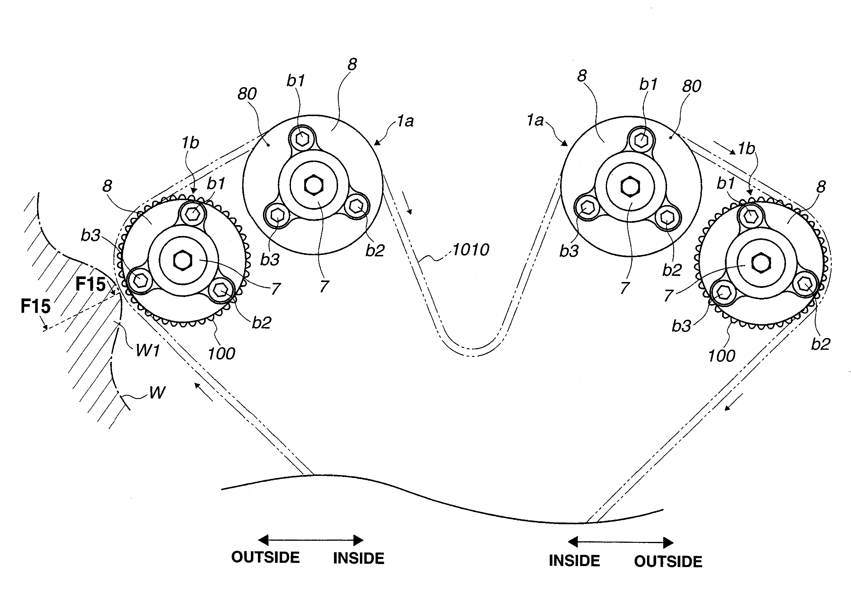
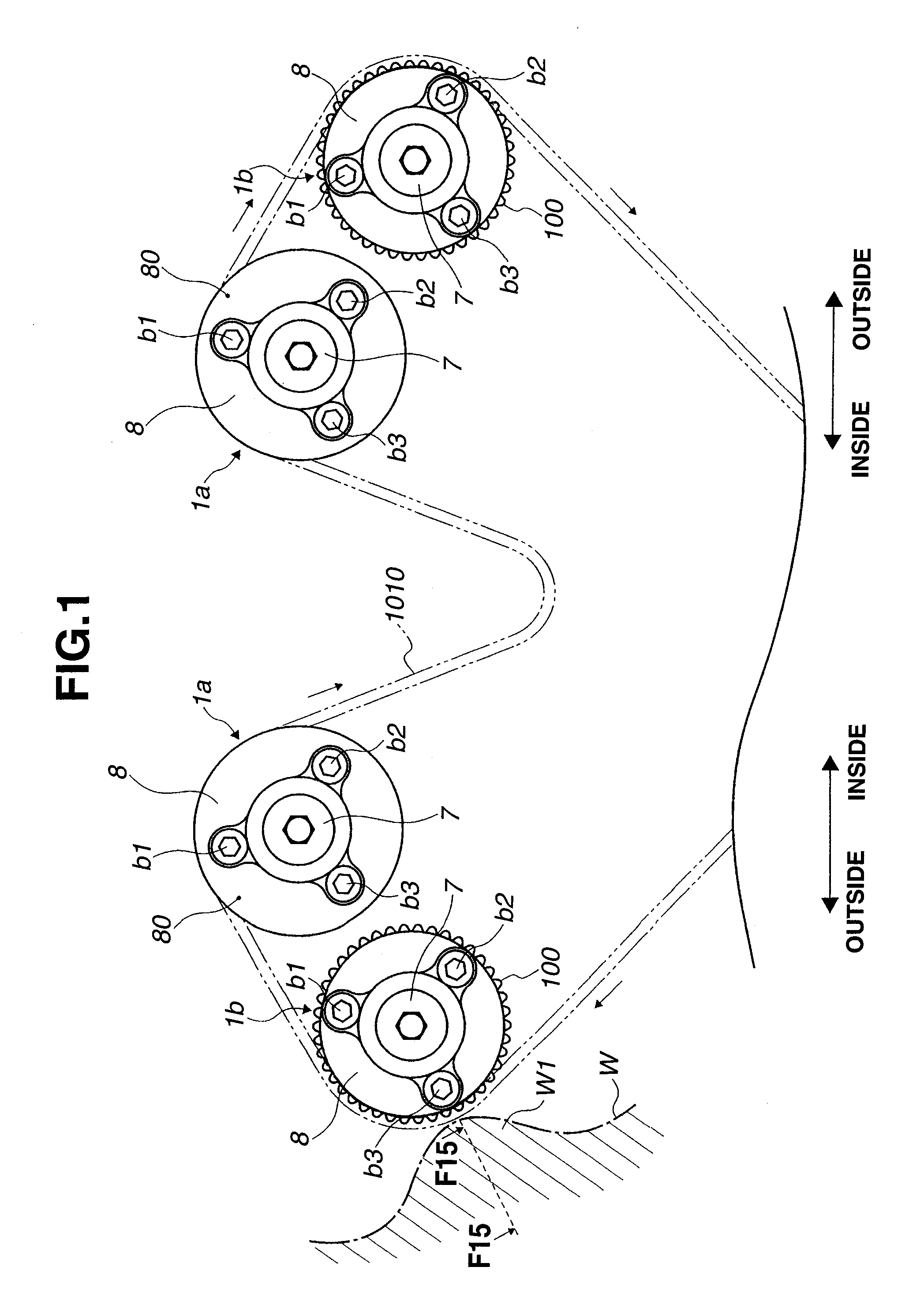
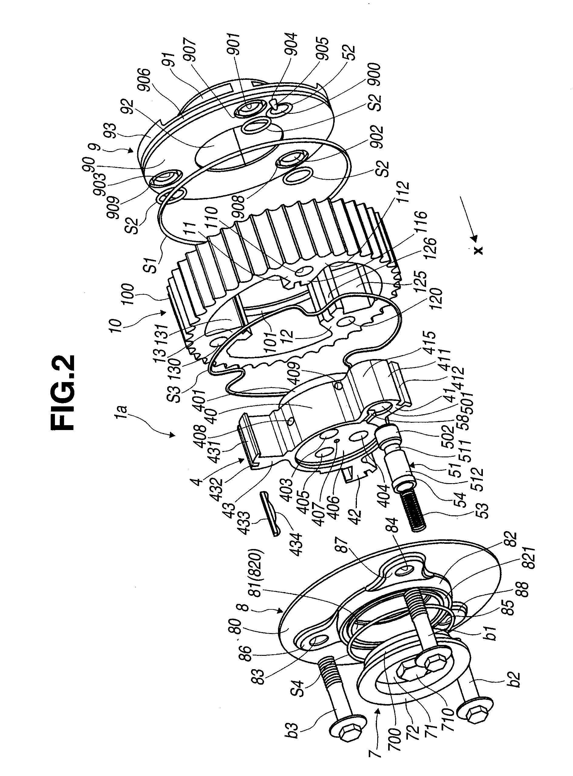
[0030]>FIG. 1 is a front view of a valve timing control apparatus according to an embodiment of the present invention in which a pair of intake valve timing control apparatuses 1a and a pair of exhaust valve timing control apparatuses 1b are mounted to an internal combustion engine, as viewed in an axial direction of the internal combustion engine. The axial direction is an axial direction of a crankshaft of the internal combustion engine, which is identical to an axial direction of intake camshafts or exhaust camshafts. The intake valve timing control apparatus 1a and exhaust valve timing control apparatus 1b are individually or collectively referred to as valve timing control apparatus or system 1. The internal combustion engine is arranged in a vehicle engine room so that the axial directions of the crankshafts and camshafts are perpendicular to a vehicle longitudinal direction. In other words, FIG. 1 is a view of valve timing control apparatus 1 in a vehicle lateral direction. I...


PUM


Abstract

A valve timing control apparatus for an internal combustion engine, includes a housing body, a sealing plate, a vane rotor, and a sealing ring. The housing body includes an opening at an axial end which is closed by the sealing plate. The sealing ring is disposed between the housing body and the sealing plate. The housing body is formed of an aluminum-based metal material and anodized, wherein the housing body includes a base layer and an anodic oxide coating film layer. The sealing ring abuts on the base layer of the housing body at the axial end.

Description

BACKGROUND OF THE INVENTION[0001]The present invention relates to valve timing control apparatuses for internal combustion engines, and methods of producing same.[0002]Japanese Patent Application Publication No. 5-113112 discloses a valve timing control apparatus for an internal combustion engine, which includes a housing connected to a crankshaft, and a phase change mechanism mounted in the housing, and connected to a camshaft. The housing is formed with a pulley at its outside periphery to which torque is transmitted from the crankshaft through a timing belt that is wound around the pulley, so that the housing rotates in synchronization with the crankshaft. The phase change mechanism operates in response to supply and drainage of working fluid, for changing valve timing, i.e. rotational phase of the camshaft with respect to the crankshaft.SUMMARY OF THE INVENTION[0003]The valve timing control apparatus described above is subject to a problem that the timing belt may be degraded by...

Claims


Application Information

Patent Timeline
IPC IPC(8): F01L1/34
CPCF01L1/02F01L1/024F01L2103/00F01L2001/34479F01L1/3442F01L2303/00
Inventor WATANABE, ATSUSHI
Owner HITACHI AUTOMOTIVE SYST LTD
Learn More