
Roll suppression device for offshore structure

a technology for offshore structures and suppression devices, which is applied in the direction of foil-based vessel movement reduction, special-purpose vessels, vessel construction, etc., can solve the problems of no example of practical application to offshore structures, entail serious risks, and the bilge-keel is not particularly effective at reducing rolling, so as to reduce the roll due effect, improve the stability and work efficiency of offshore structures, and remove risks

Inactive Publication Date: 2011-03-17
DAEWOO SHIPBUILDING & MARINE ENG CO LTD
View PDF9 Cites 15 Cited by
  • Summary
  • Abstract
  • Description
  • Claims
  • Application Information

AI Technical Summary

Benefits of technology

The present patent is about a device that reduces the rolling of an offshore structure caused by waves. It improves the stability and work efficiency of the offshore structure at sea and removes risks during shuttle docking or ship-to-ship operation. The device includes a connection unit that protrudes downward from the bottom of the offshore structure and a damping plate that is connected to the connection unit and separated from the bottom. The damping plate can be positioned along either side of the bottom or at the bottom of the offshore structure. It can also be reinforced with a reinforcement member secured to the damping plate and the connection unit. The device can be detachably connected to the connection unit.

Problems solved by technology

A conventional offshore structure employs the bilge-keel to reduce rolling, but the bilge-keel is not particularly effective at reducing rolling, since it cannot be designed beyond the bilge radius, lateral side and bottom of the offshore structure due to various risks.
In addition, not only do devices for actively suppressing roll of the offshore structure, i.e., an anti-roll tank, a fin stabilizer, etc. have a complicated structure, but also there is no example of practical application to the offshore structure due to issues in maintenance, effect, etc.
Moreover, a step, a skirt and the like are considered in light of a large bilge-keel, but entail a serious risk during shuttle docking or ship-to-ship offloading, since they are directly mounted to a base line.

Method used


Image

  • Roll suppression device for offshore structure
  • Roll suppression device for offshore structure
  • Roll suppression device for offshore structure

Examples


Embodiment Construction

[0016]Exemplary embodiments of the present disclosure will be now described in detail with reference to the accompanying drawings. The following embodiments are given by way of illustration to provide a thorough understanding of the invention to those skilled in the art. Hence, it should be understood that other embodiments will be evident based on the present disclosure, and that system, process or mechanical changes may be made without departing from the scope of the present disclosure.

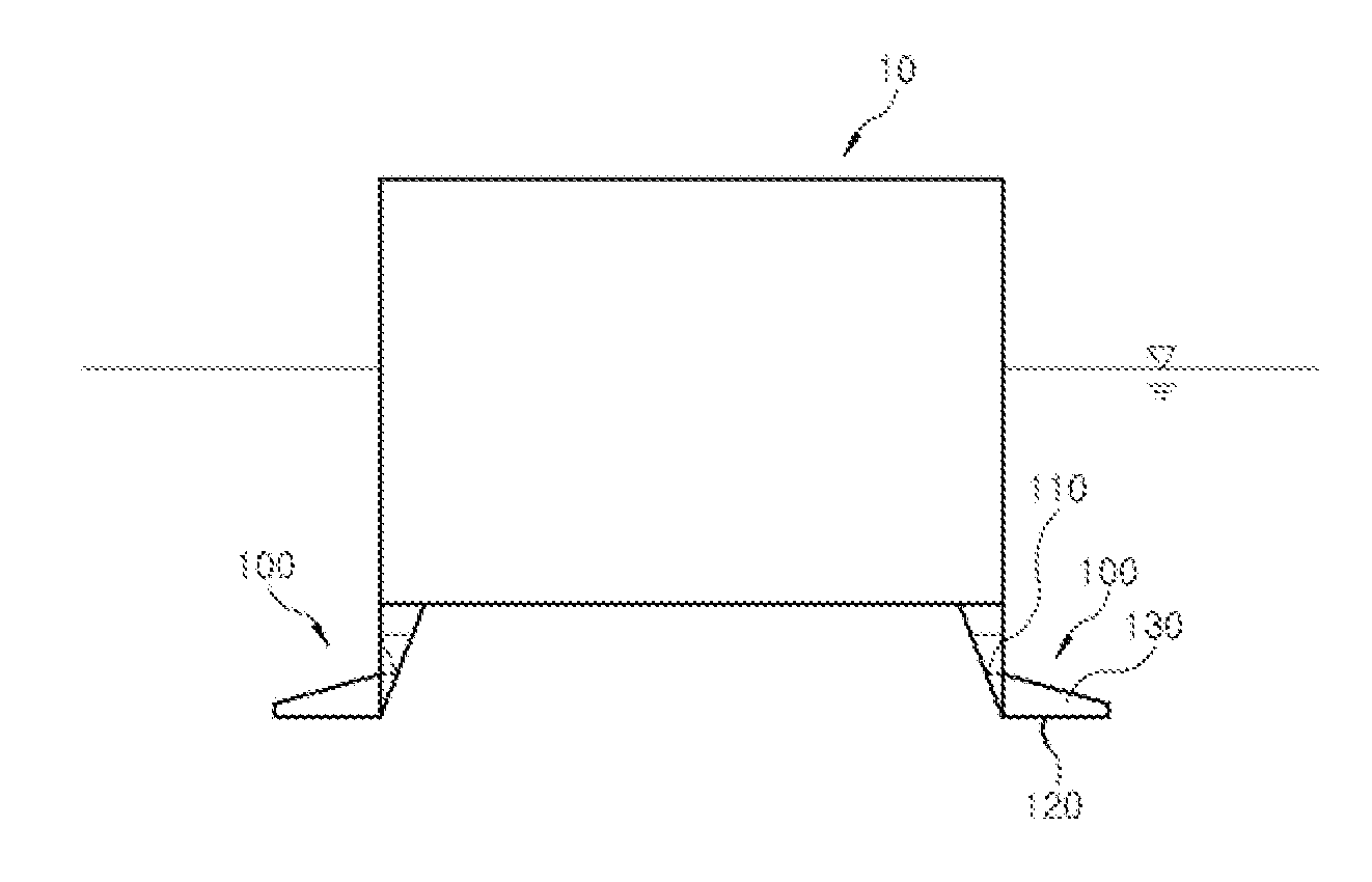
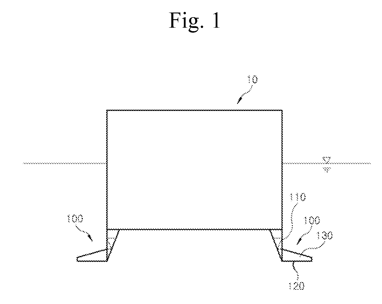
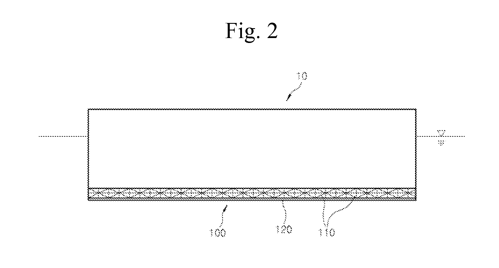
[0017]FIG. 1 is a front view of a roll-suppression device for an offshore structure in accordance with one exemplary embodiment of the present disclosure, and FIG. 2 is a side view of the roll-suppression device in accordance with the exemplary embodiment of the present disclosure. Referring to FIGS. 1 and 2, a roll-suppression device 100 for an offshore structure 10 according to this embodiment includes a connection unit 110 under the bottom of the offshore structure 10, and a damping plate 120 con...


PUM


Abstract

The present disclosure relates to a roll-suppression device for an offshore structure. The device includes a damping plate separated downward from a hull to be placed below a bottom of the offshore structure by a connection unit, so that the width of the damping plate may be effectively enlarged without occurrence of collision during shuttle docking or ship-to-ship operation. Accordingly, the device may maximize roll-suppression, as compared with a bilge-keel or a step, and a detachable design of the device facilitates ship construction or shore operation inside a drydock.

Description

BACKGROUND[0001]1. Technical Field[0002]The present disclosure relates to a roll-suppression device for an offshore structure and, more particularly, to a roll-suppression device for an offshore structure that enables enlargement of a width of a damping plate for suppressing roll of the offshore structure in order to maximize the effect of suppressing the roll and is configured to eliminate a risk of collision of the damping plate having the enlarged width with other ships during shuttle docking or ship-to-ship operation. Further, this device has a detachable structure so as to enable a building operation within a dock or a outfitting operation at shore.[0003]2. Description of the Related Art[0004]In general, an offshore structure is shaped like a ship or a barge, such as floating production storage offloading (FPSO), liquefied natural gas floating production storage offloading (LNG FPSO), floating storage and re-gasification unit (FSRU), etc., which moves in various directions by w...

Claims


Application Information

Patent Timeline
Patent Type & Authority Applications(United States)
IPC IPC(8): B63B39/06
CPCB63B39/06B63B1/32B63B1/26
Inventor LEE, JUNG HANKIM, YONG SOOWOO, JE HYOUKKIM, DAE WOONGPARK, SUNG GUNNAHM, JONG OUPARK, BYEONG WON
Owner DAEWOO SHIPBUILDING & MARINE ENG CO LTD
Learn More