
Diagnostic system and method for home appliance

Active Publication Date: 2011-03-03
LG ELECTRONICS INC
View PDF41 Cites 17 Cited by
  • Summary
  • Abstract
  • Description
  • Claims
  • Application Information

AI Technical Summary

Benefits of technology

[0016]It is another object of the present invention to provide a diagnostic system and method for a home appliance wherein the state of the home appliance is determined and a fault thereof is diagnosed using product information extracted from an output sound signal to achieve correct fault diagnosis for the home appliance and also to enable rapid after-sale service for the home appliance.

Problems solved by technology

For this reason, the user may have difficulty in coping with the fault in the home appliance and in accurately communicating the state of the home appliance to the service center even though contacting the service center.
Consequently, when a service technician visits the user's home, a lot of time and cost may be taken for the service technician to repair the home appliance due to lack of accurate prior knowledge as to the state of the home appliance.
For example, provided that a part required for repair of the home appliance is not prepared in advance, the service technician will have the inconvenience of re-visiting the user's home, resulting in an increase in repair time.
However, this technique requires continuous connection of the modem to the home appliance.
Particularly, in the case where the home appliance is a laundry treatment machine that is usually installed outdoors, a spatial restriction may be imposed on connecting the laundry treatment machine to the telephone network.
Signal interference may occur depending on an ambient environment in the course of converting the fault information of the home appliance into the sound signal of the audible frequency band and then transmitting the sound signal to a receiver of the telephone.
In addition, data may be lost according to characteristics of the telephone network during the transmission of the sound signal over the telephone network.
However, the conventional system has suggested no detailed scheme for performing diagnosis on the state of the home appliance.

Method used


Image

  • Diagnostic system and method for home appliance
  • Diagnostic system and method for home appliance
  • Diagnostic system and method for home appliance

Examples


Embodiment Construction

[0030]Reference will now be made in detail to the preferred embodiments of the present invention, examples of which are illustrated in the accompanying drawings. Wherever possible, the same reference numbers will be used throughout the drawings to refer to the same or like parts.

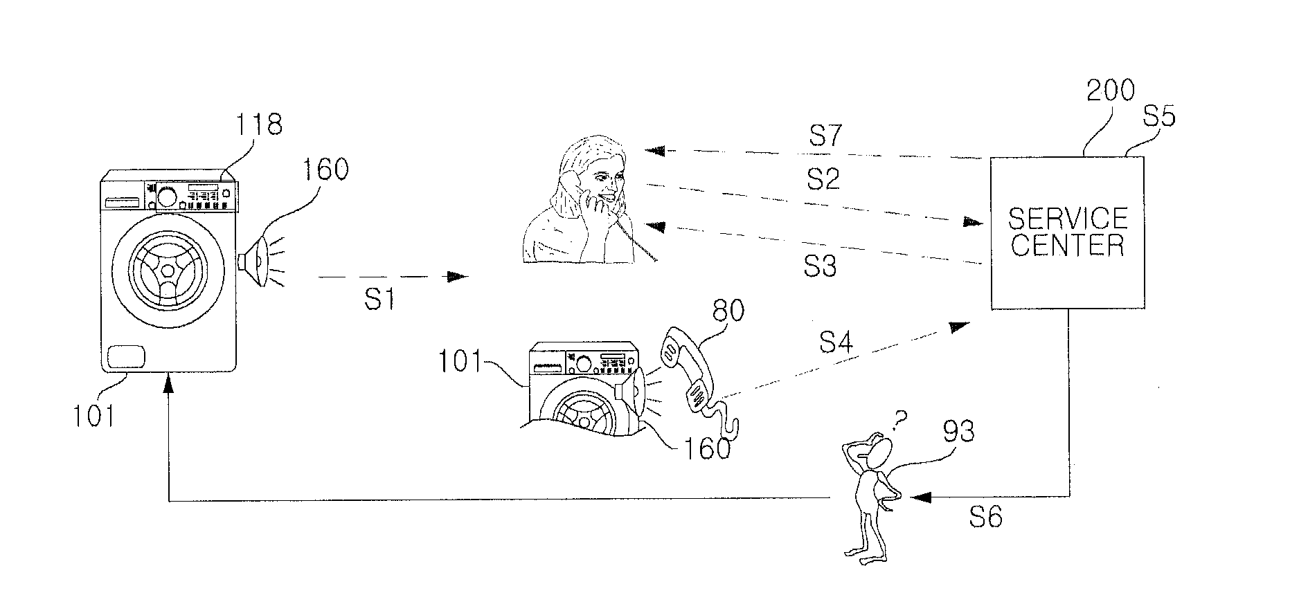
[0031]FIG. 1 is a schematic view showing the configuration of a home appliance diagnostic system according to an embodiment of the present invention.

[0032]Referring to FIG. 1, a home appliance of the present invention is configured in such a manner that, when a home appliance 101 in each home outputs information about the operation thereof in the form of a sound signal, the sound signal, which includes product information, is input to a portable terminal such as a mobile phone or a telephone and is then transmitted to a service center 200 over a telephone network so that a diagnostic server in the service center 200 may diagnose the state of the home appliance 101 to determine whether the home appliance 101 ...


PUM


Abstract

A diagnostic system and method for a home appliance is provided. When the home appliance outputs product information as a sound signal, a service center remotely performs fault diagnosis of the home appliance by receiving the sound signal, detecting the product information from the sound signal, checking the state of the home appliance using diagnostic data included in the product information to determine whether the home appliance is out of order, determining, when a drying error has occurred, a cause of the drying error, and deriving a solution to the drying error. Upon deriving a diagnosis result through the fault diagnosis of the home appliance, the service center immediately notifies the user of the diagnosis result and may dispatch a service technician or may provide the user with a solution to allow the user to easily fix the fault without dispatching a service technician.

Description

CROSS-REFERENCE TO RELATED APPLICATION[0001]This application claims the priority benefit of Korean Patent Application No. 10-2009-0071047, filed on Jul. 31, 2009 in the Korean Intellectual Property Office, and U.S. Provisional Patent Application No. 61 / 230,578 filed on Jul. 31, 2009 in the USPTO, the disclosure of which is incorporated herein by reference.BACKGROUND OF THE INVENTION[0002]1. Field of the Invention[0003]The present invention relates to a diagnostic system and method for a home appliance, and more particularly to a home appliance diagnostic system and method for performing state inspection and fault diagnosis of a home appliance based on product information of the home appliance, which is output as a sound signal, to facilitate after-sale service for the home appliance.[0004]2. Description of the Related Art[0005]In operation, a home appliance stores values set for execution of the operation, information generated during the operation, fault information, etc. Particula...

Claims


Application Information

Patent Timeline
IPC IPC(8): G06Q10/00G06F15/00
CPCH04L12/2825G06Q10/06311H04L12/12
Inventor HAN, JONGHYECHO, INHAENGLEE, PHALJINJEONG, HOIJIN
Owner LG ELECTRONICS INC
Learn More