
Exhaust system

a technology of exhaust system and exhaust pipe, which is applied in ventilation system, lighting and heating apparatus, heating type, etc., can solve the problems of difficult to provide exhaust pipe in rooms where construction work is taking pla

Active Publication Date: 2011-03-03
DEAN JEROME
View PDF29 Cites 0 Cited by
  • Summary
  • Abstract
  • Description
  • Claims
  • Application Information

AI Technical Summary

Benefits of technology

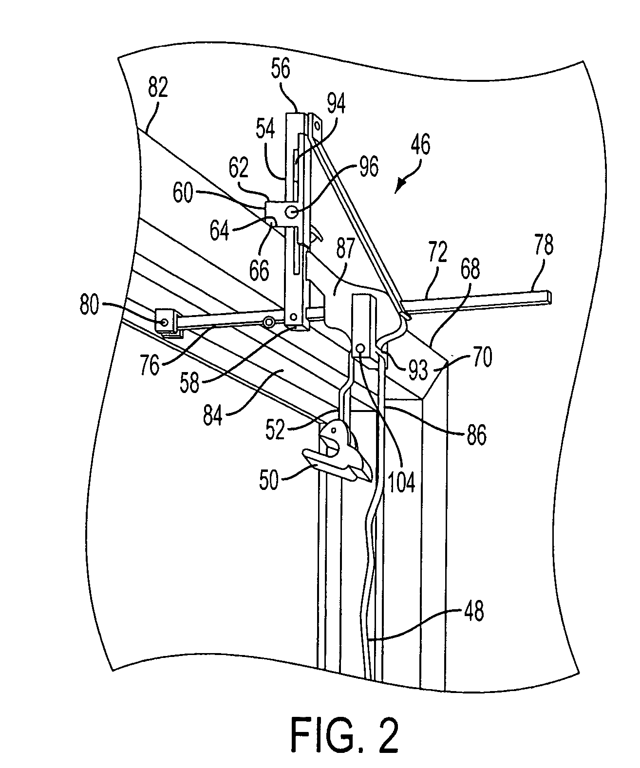
[0008]It is a further object of the present invention to provide an exhaust system wherein a tension screw is interposed between the vertical bracket and the support block to allow for selective release of the support block allowing for controlled movement of the support block relative to the vertical bracket.
[0015]It is also an object of the present invention to provide an exhaust system wherein the strap stop includes a rod held within a tapered slot such that the rod may be moved from a wide end of the tapered slot to a narrow end of the tapered slot creating friction holding the strap in place.

Problems solved by technology

As those working within the construction industry will readily acknowledge providing for the exhaust of rooms in which construction work is taking place can be difficult given the variable sizes of the windows within the room and the framework surrounding the windows.

Method used


Image

  • Exhaust system
  • Exhaust system
  • Exhaust system

Examples


Embodiment Construction

[0026]The detailed embodiments of the present invention are disclosed herein. It should be understood, however, that the disclosed embodiments are merely exemplary of the invention, which may be embodied in various forms. Therefore, the details disclosed herein are not to be interpreted as limiting, but merely as a basis for teaching one skilled in the art how to make and / or use the invention.

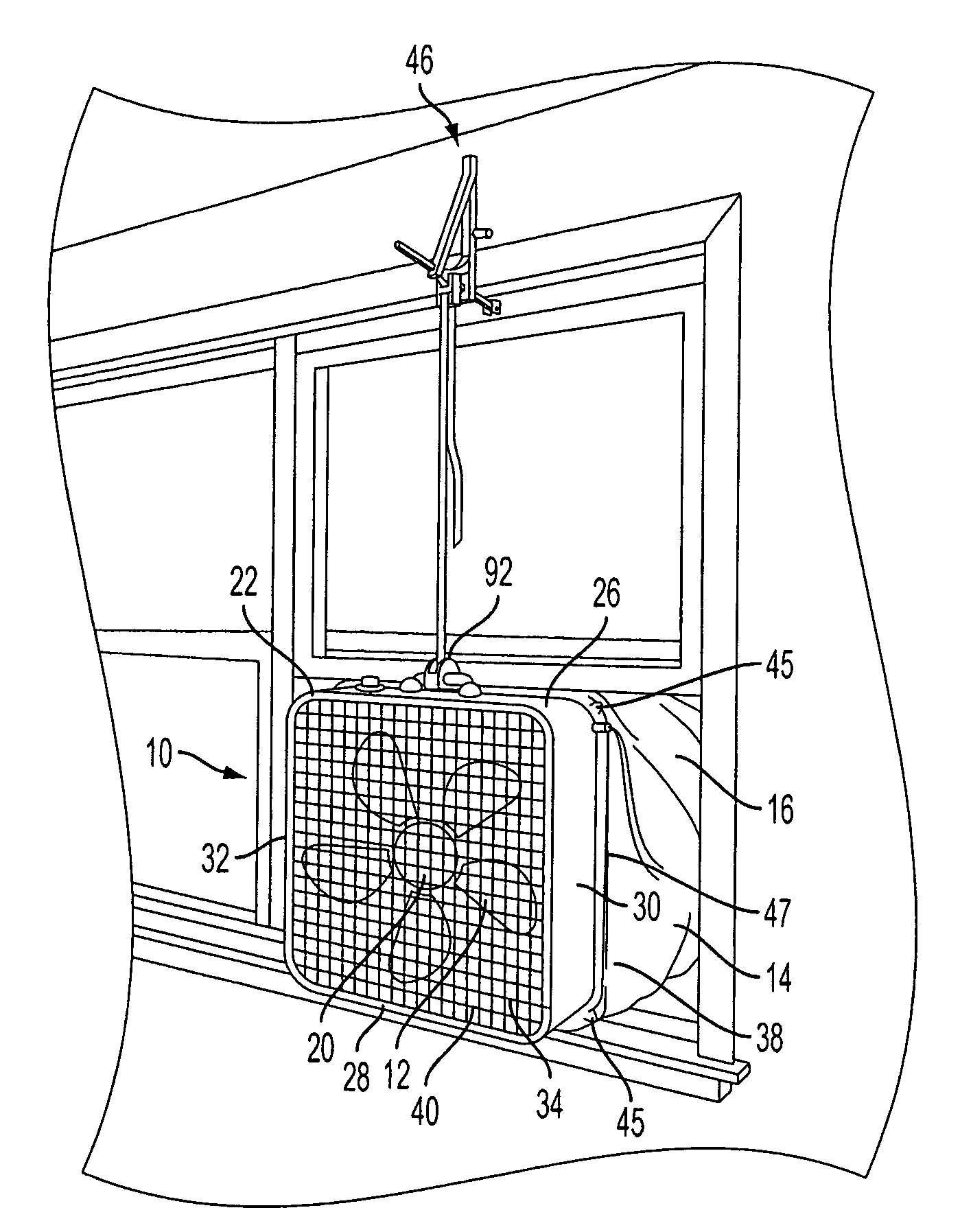
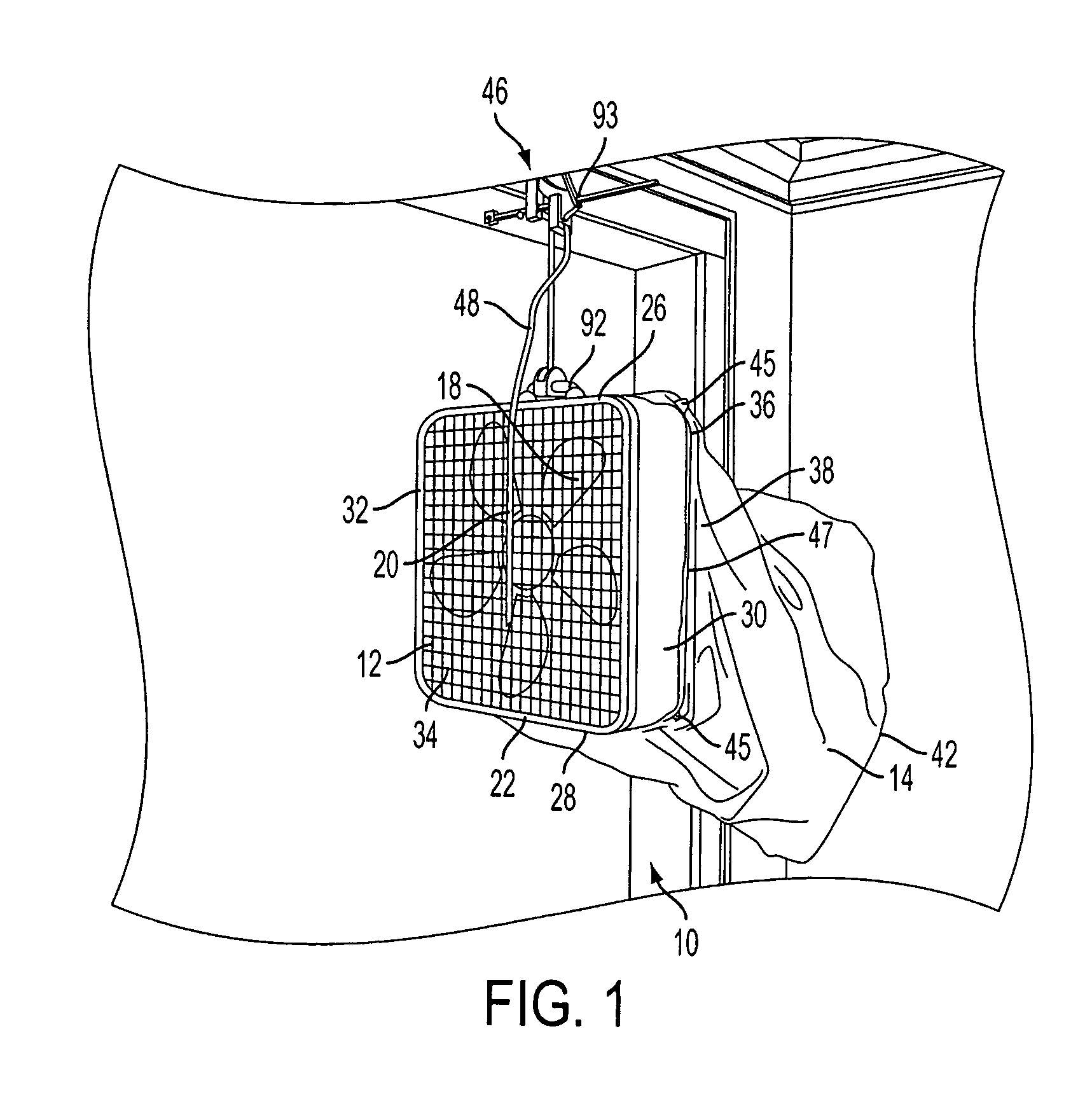
[0027]In accordance with the present invention, and with reference to embodiments disclosed in FIGS. 1 to 7, an exhaust system 10 composed of an exhaust fan 12 and associated flexible exhaust boot 14 are disclosed. The exhaust boot 14 is secured to the exhaust fan 12 and the exhaust fan 12 is placed near a window 16 or other opening with the exhaust boot 14 facing the external environment. When the fan blades 18 of the exhaust fan 12 rotate, they force the exhaust boot 14 to expand thereby filling the opening of the window 16 in which the exhaust fan 12 is positioned and extending outside in a ...


PUM


Abstract

An exhaust system includes an exhaust fan having a frame within which fan blades and a motor are secured. The frame includes an upper sidewall, a bottom sidewall, a first lateral sidewall and a second lateral sidewall, defining an inlet opening and an outlet opening on opposite sides of the frame. A flexible exhaust boot is secured to the frame of the exhaust fan adjacent the outlet opening. The exhaust boot is a flexible piece of material having a substantially tubular configuration with a first end having an opening and a second end having an opening. A support assembly secures the exhaust fan and exhaust boot in position adjacent an opening. The support assembly includes a vertical bracket having a first end and a second end, and an outwardly extending support block is mounted at the first end of the vertical bracket. The support assembly also includes a horizontal bracket extending substantially perpendicular to the vertical bracket. The horizontal bracket is shaped and dimensioned to pass through a connection opening in the second end of the vertical bracket, and the horizontal bracket includes first end and a second end. The first end of the horizontal bracket extends outwardly from the same side of the vertical bracket as the support block. A strap is selectively connected to the exhaust fan.

Description

BACKGROUND OF THE INVENTION[0001]1. Field of the Invention[0002]The present invention relates to an exhaust system for drawing air and dust from an enclosed room to an external environment. More particularly, the invention relates to an exhaust system composed of an exhaust fan with an exhaust boot secured thereto, the exhaust fan and exhaust boot being secured within a window opening via a support assembly.[0003]2. Description of the Related Art[0004]As those working within the construction industry will readily acknowledge providing for the exhaust of rooms in which construction work is taking place can be difficult given the variable sizes of the windows within the room and the framework surrounding the windows. The present invention provides a portable exhaust system allowing for use in conjunction with various window openings and in conjunction with various framework that might be surrounding a window.SUMMARY OF THE INVENTION[0005]It is, therefore, an object of the present inve...

Claims


Application Information

Patent Timeline
Patent Type & Authority Applications(United States)
IPC IPC(8): F24F7/013
CPCB08B15/02F24F2007/001F24F7/013
Inventor DEAN, JEROME
Owner DEAN JEROME
Learn More