Aerofoil slot blowing

a technology of air slot and airbag, which is applied in the field of airbags, can solve the problems of increasing drag, affecting affecting the noise of aircraft, so as to improve the performance of airbags, improve the airbag performance, and improve the effect of airbag performan

Inactive Publication Date: 2011-03-03
AIRBUS OPERATIONS LTD
View PDF5 Cites 4 Cited by
  • Summary
  • Abstract
  • Description
  • Claims
  • Application Information

AI Technical Summary

Benefits of technology

[0012]A further aspect of the invention provides a method of improving the performance of an aerofoil defining geometric upper and lower surfaces which together form a leading edge region and a trailing edge region, the method comprising injecting fluid into the airflow over the aerofoil from a slot in the lower geometric surface, which is located forward of the leading edge stagnation point at the critical angle of incidence of the aerofoil, the fluid being injected into the airflow in a forward direction from the slot and substantially parallel to the lower surface.
[0013]The invention is advantageous in that the blown slot can entrain (energise) the boundary layer to keep it attached so as to provide high lift performance when the aerofoil is at high incidence. By providing the blown slot on the lower geometric surface, the upper surface of the aerofoil can be kept “clean”, i.e. free of aerodynamic steps, giving the potential for laminar flow during cruise.
[0016]The slot preferably extends spanwise across the leading edge region. The slot preferably has a width of small dimension, less than 1 mm, and most preferably less than 0.3 mm. The size of the slot is only limited by manufacturing tolerances. The effectiveness of the blowing slot is improved by decreasing the slot width and / or increasing the velocity of the fluid injected into the airflow.

Problems solved by technology

However, leading edge slats are becoming one of the greatest sources of aircraft noise during the landing phase.
This turbulent flow increases drag.
Laminar aerofoils require “clean” (smooth) leading edge profiles, which conflict with traditional high lift devices, such as slats.
This is undesirable for a laminar aerofoil, as the step in the leading edge region 5 will trip the laminar boundary layer when the aerofoil is at low angles of incidence, such as during cruise.

Method used


Image

  • Aerofoil slot blowing
  • Aerofoil slot blowing

Examples


Embodiment Construction

)

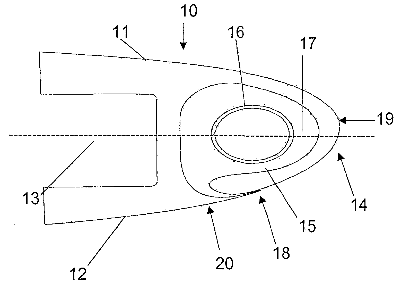
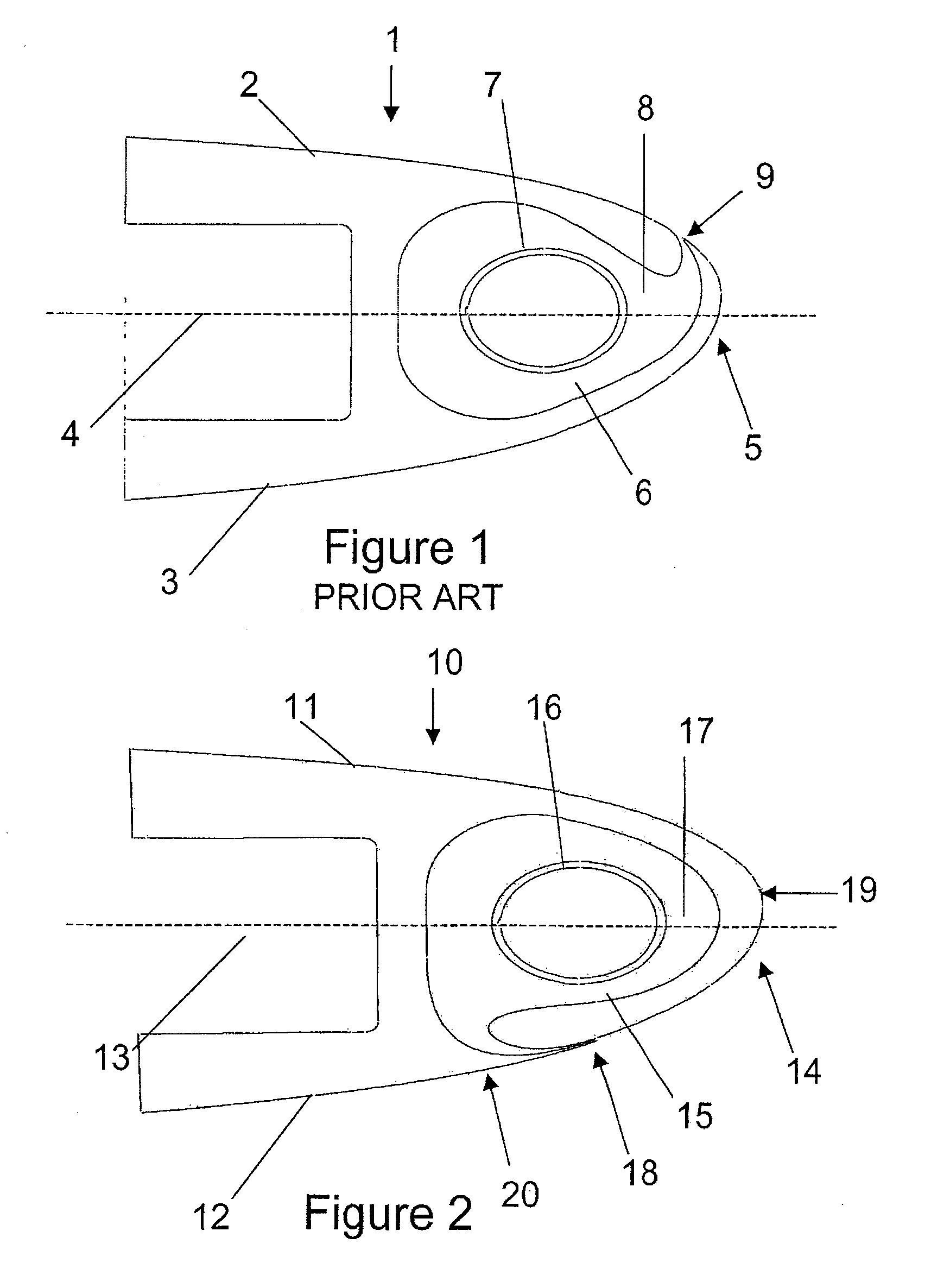
[0023]FIG. 2 shows a schematic cross section view of an aerofoil leading edge including a leading edge slot blowing device. As can be seen from FIG. 2, the aerofoil 10 has upper and lower geometric surfaces 11, 12 on either side of the chord line 13 and which together form a leading edge region 14. The upper and lower surfaces also meet to form a trailing edge region (not shown). Behind the leading edge region 14 is a blowing device 15. The blowing device 15 includes a piccolo tube 16 which carries a supply of high pressure air in the spanwise direction behind the leading edge. The piccolo tube 16 expels the high pressure air radially into a cavity 17, which is shaped to accelerate the air through a slot 18 extending spanwise across the lower surface 12.

[0024]The blowing device 15, when activated, injects the air into the airflow over the aerofoil 10 forwardly from the slot 18, substantially parallel to the lower surface 12, and around the leading edge region 14 in a chordwise dire...


PUM


Abstract

An aerofoil defining geometric upper and lower surfaces which together form a leading edge region and a trailing edge region, and comprising a blowing device having a slot in the lower geometric surface in the leading edge region for injecting fluid into the airflow over the aerofoil, wherein the slot is located forward of the leading edge stagnation point at the critical angle of incidence of the aerofoil, and wherein the blowing device is adapted to inject the fluid forwardly of the slot and substantially parallel to the lower surface. Also, a method of improving the performance of the aerofoil by injecting fluid into the airflow over the aerofoil from the slot. The upper surface of the aerofoil can be kept clean, giving the potential for laminar flow during cruise without significantly compromising the high lift performance of a blown leading edge at high incidence.

Description

FIELD OF THE INVENTION[0001]The present invention relates to an aerofoil having a blowing slot in its leading edge for injecting fluid into the airflow over the aerofoil.BACKGROUND OF THE INVENTION[0002]An aerofoil is a streamlined body that generates lift when moved relative to the surrounding air. Aerofoils, such as aircraft wings and horizontal tailplanes, have upper and lower geometric surfaces which together form a leading edge region and a trailing edge region.[0003]To improve the lift performance of the aerofoil at high angles of attack, various leading edge high lift devices, such as slats and flaps, have been developed. Many aircraft have slats mounted to the wing fixed leading edge, which are deployed forwardly during take-off and landing to increase the lift coefficient of the wing. They are typically retracted during cruise to reduce drag. High lift devices increase payload and performance during take-off and landing, which gives rise to significant efficiencies for the ...

Claims


Application Information

Patent Timeline
IPC IPC(8): B64C21/04
CPCY02T50/166B64C21/04Y02T50/10
Inventor BROWN, JAMES
Owner AIRBUS OPERATIONS LTD
Why Eureka
Try Eureka