
Retaining device, especially for flat roof drains

a technology for retaining devices and roof drains, applied in gravity filters, loose filtering materials, stationary filtering elements, etc., can solve the problems of little flexibility of known retaining devices, and achieve the effect of providing step-less adjustment of holding forces of retaining devices

Active Publication Date: 2011-03-03
BST KOCH KUNSTTECH +1
View PDF6 Cites 2 Cited by
  • Summary
  • Abstract
  • Description
  • Claims
  • Application Information

AI Technical Summary

Benefits of technology

One advantage of the retaining device of the invention is that it is extremely flexible.
Another advantage of the retaining device is that it provides step-less adjustability of holding forces of the retaining device, even at different sizes of a drain.

Problems solved by technology

However, this construction results in the disadvantage that suitably adapted ones of the known retaining device need to be manufactured for different respective applications so that the known retaining device is of little flexibility.

Method used


Image

  • Retaining device, especially for flat roof drains
  • Retaining device, especially for flat roof drains

Examples


Embodiment Construction

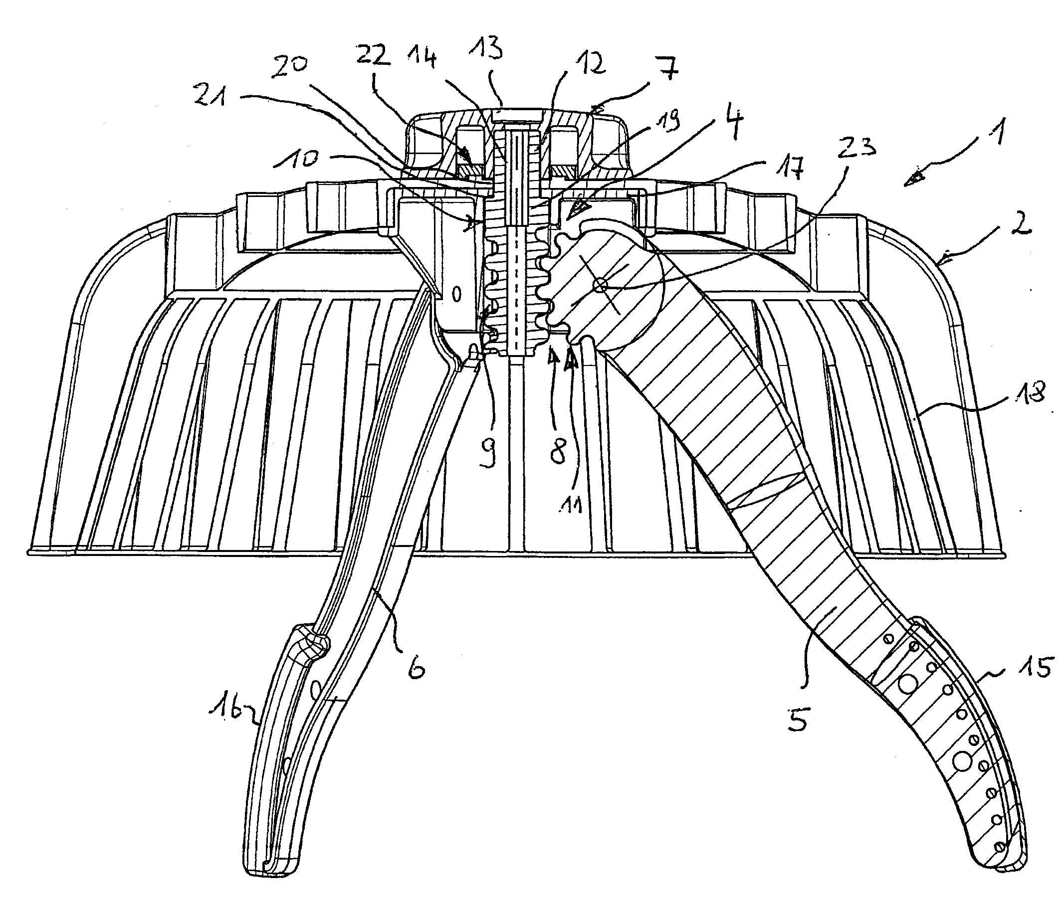
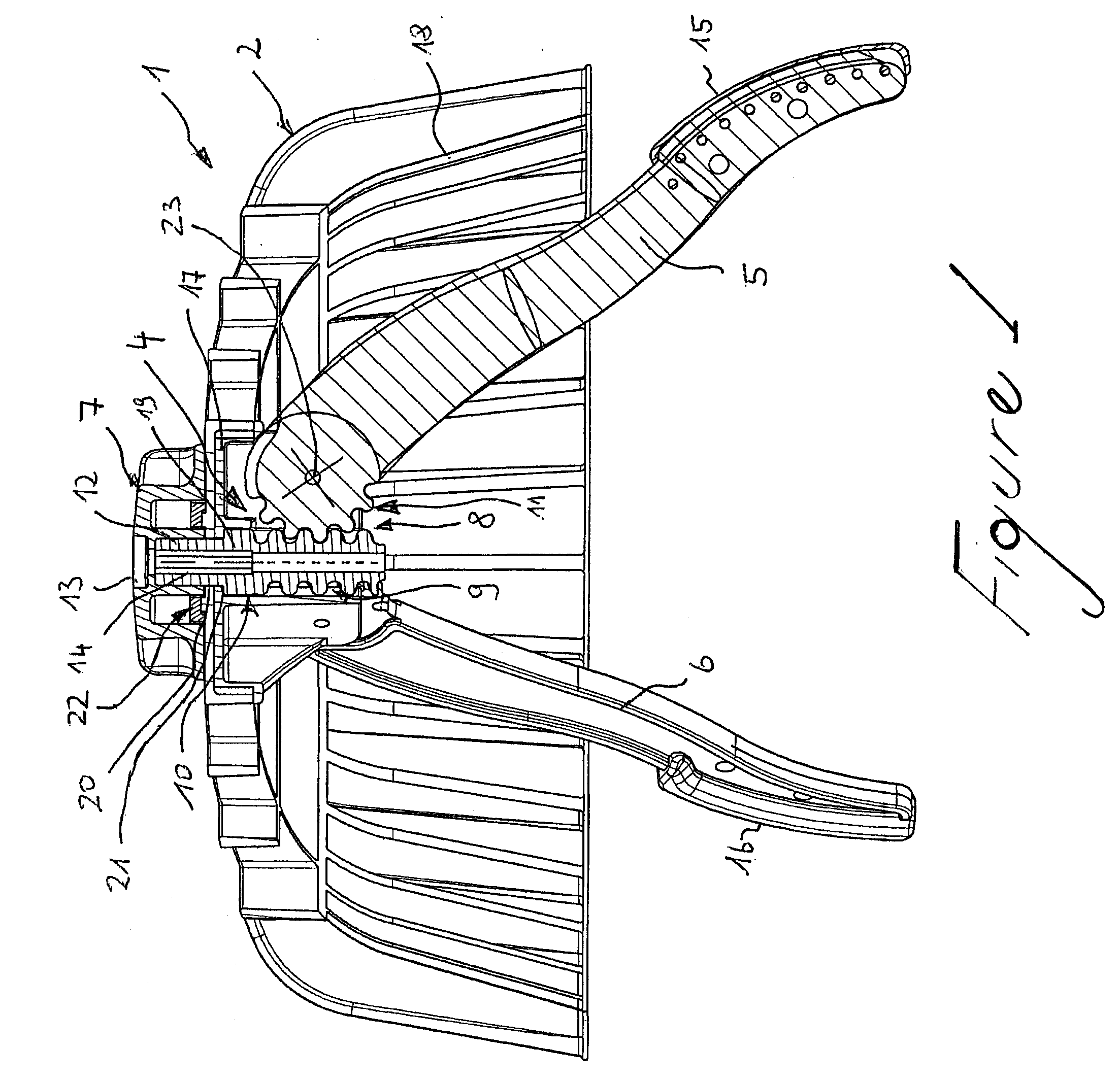
Referring now to FIG. 1 (hereinafter referred to as “the FIGURE”), an embodiment of a retaining device of the invention is generally indicated at 1. The retaining device 1 is adapted to be used with a drain (not shown) of a roof (not shown), in general, and a flat roof, in particular. However, it should be appreciated by those having ordinary skill in the related art that the retaining device 1 is not limited to such use. It should be so appreciated also that the drain can be any suitable drain and the roof can be any suitable roof.

Still referring to the FIGURE, the retaining device 1 comprises, in general, a cup-shaped trap basket 2 including a circular support edge 3. A holder 4 is disposed at the trap basket 2, includes at least two holding arms 5, 6 movable between a “holding” position and a “release” position, and is a separate assembly adapted to be connected to the trap basket 2. A gear unit 8 includes a bolt 10 that is adapted to be connected with a rotatable operating eleme...


PUM

PropertyMeasurementUnit
Angleaaaaaaaaaa

Abstract

A retaining device 1 comprises a cup-shaped trap basket 2 including a circular support edge 3. A holder 4 is disposed at the trap basket 2, includes at least two holding arms 5, 6 movable between a “holding position” and “release” position, and is a separate assembly adapted to be connected to the trap basket 2. A gear unit 8 includes a bolt 10 that is adapted to be connected with a rotatable operating element 7 and has a driving worm 9 and tooth sections 11 adapted to be engaged with the driving worm 9 and disposed at the holding arms 5, 6.

Description

BACKGROUND OF INVENTION1. Field of InventionThe invention relates, generally, to a retaining device and, more particularly, to such a device used especially for flat-roof drains.2. Description of Related ArtA known retaining device covering a drain of a roof, in general, and a flat roof, in particular, is used to prevent infiltration of the drain by pollution—such as debris, gravel, leaves, and other possibly blocking materials. Hence, in practice, such retaining device is often designated as a “gravel-trap basket” or “leaves-trap basket.”For this purpose, the known retaining device comprises a cup-shaped trap basket provided, in general, with rib units that are able to drain water, but can retain polluting materials, such as leaves, gravel, or the like. The trap basket has a support edge, is set to a roof region that encircles the drain, and is removably attached by a bracket. For this purpose, holding arms protruding into the drain are typically provided.The known retaining device...

Claims


Application Information

Patent Timeline
IPC IPC(8): B01D35/28E04D13/04
CPCE04D2013/0413E04D13/0409
Inventor SCHOELL, MAXIMILIANZIMMERMANN, MICHAEL
Owner BST KOCH KUNSTTECH
Learn More