
Single cylinder hydraulic log lifter

a single-cylinder, hydraulic technology, applied in the direction of flat surface machines, load-engaging elements, profiling/shaping machines, etc., can solve the problems of curtailment of mobility, high cost of hydraulically powered log lifters, and high cos

Inactive Publication Date: 2011-03-03
HICKS NORMAN A
View PDF11 Cites 5 Cited by
  • Summary
  • Abstract
  • Description
  • Claims
  • Application Information

AI Technical Summary

Benefits of technology

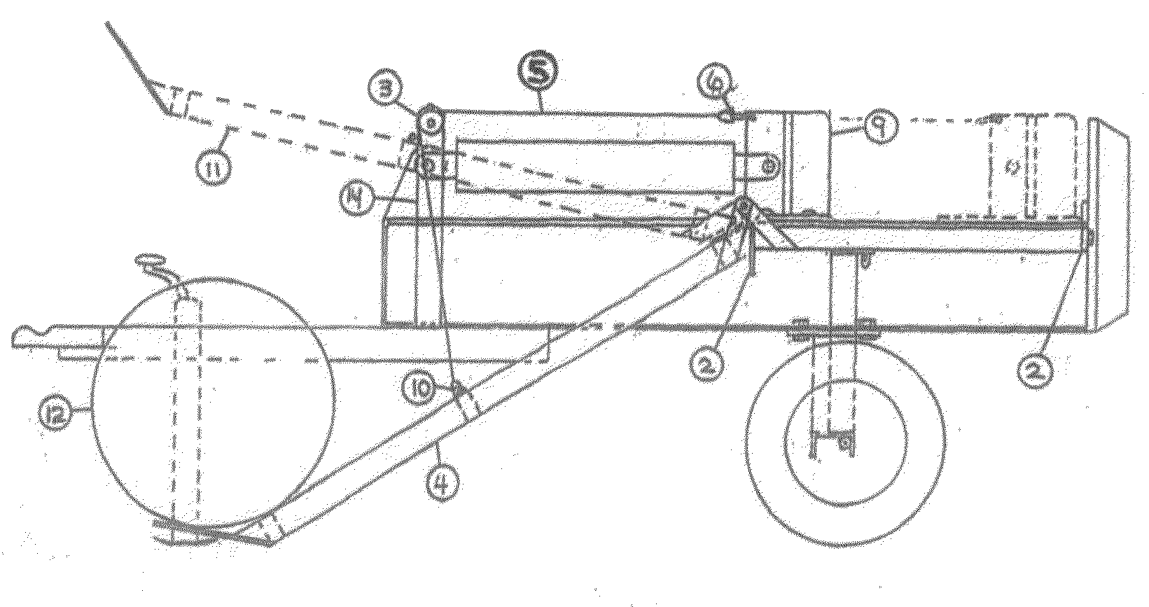
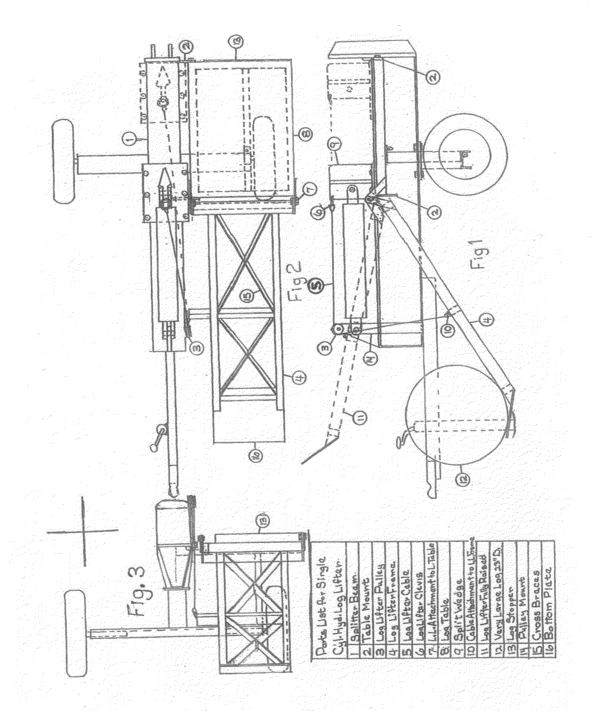
[0009]The invention consists of a log splitter equipped with a log lifter attached to a large log table in a hinged fashion, and being raised hydraulically by the same cylinder that powers the split wedge. This eliminates the need for a second cylinder, second control valve, and extra hoses and fittings normally required for a log lifter, thereby considerably reducing the overall costs of having a log lifter available for those large logs. A cable attached to the log lifter, runs up over a pulley fixed to the beam and thence to the top, rear end of the split wedge. The operator places the log on the log lifter, then attaches the cable to the split wedge, then powers the split wedge forward using the control valve, and the log is raised. The log rolls to the table and the operator moves it wholly onto the table. Then he returns the split wedge to its retruded position, unhooks the cable from the split wedge, and sets it aside. This only requires a few seconds. He then proceeds to split the log in normal fashion. An added extra is that the log table is permanently available to hold the pieces of the large log until they can be split down to final size.

Problems solved by technology

This requires the operator to either work in a very bent over position or to get down on his knees which curtails his mobility.
Hydraulically powered log lifters are an expensive but very handy option on many commercially available splitters.
Their only real drawback is their high cost.
They require a separate cylinder, control valve, hoses, and fittings, all of which add to their cost.
Another standard shortcoming in modern log splitters is the lack of a decent sized log table.

Method used


Image

  • Single cylinder hydraulic log lifter
  • Single cylinder hydraulic log lifter

Examples


Embodiment Construction

[0013]Since this invention is an addition to a log splitter, it is assumed that the splitter is a 22 ton horizontal only splitter with a separate tank, not part of the axle. (Although the vertical / horizontal model would be modified in just the same way except that an extra trailer jack might have to be added to the table to prevent the splitter from tipping if the table would be overloaded.) The log table (No. 8) is added to the splitter first. A piece of 7⅝×2×¼ inch steel flat, with a ½ inch hole centered 1 inch in from the end, is welded to the backstop (No. 2) and underside of the top plate of the beam. Another piece ¼×5×7⅝ inch (No. 2 at the hinge end) and notched to avoid the underside of the split wedge and with a ½ inch hole in the appropriate place to attach to the table, is welded to the underside of the beam and to the web, far enough back toward the base end of the cylinder to allow the table and its mounting brackets to fit in between the two beam mounted brackets.

[0014]...


PUM


Abstract

This invention adds a very large (24×32 inch or larger) log table permanently mounted to the log splitter. This alone adds immeasurably to the efficiency and convenience of splitting. It allows for the true, convenient, and safe one-man operation of a splitter because it catches and stores the far side of the log and log pieces while the operator is free to handle the near side with one hand and the control valve with the other hand. The log lifter is powered hydraulically with the same cylinder, control valve, hoses and fittings that power the split wedge. Very simply, a cable and a pulley are used to direct the force of the existing cylinder to raise the log lifter. This simplicity lowers the cost of the log lifter considerably and makes it and the log table and the convenience of splitting in a more comfortable, standing position more readily available to the splitting public.

Description

CROSS-REFERENCE TO RELATED APPLICATIONS[0001]Not applicableSTATEMENT REGARDING FEDERALLY SPONSORED RESEARCH OR DEVELOPMENT[0002]Not applicableTO SEQUENCE LISTING, A TABLE, OR A COMPUTER PROGRAM LISTING COMPACT DISC APPENDIX[0003]Not applicableBACKGROUND OF THE INVENTION[0004]Mechanical log splitters of various types have been available for many years. Hydraulically operated ones have become the most commonly used type now.[0005]The larger gasoline powered log splitters available today are capable of splitting logs heavier than the operators can or care to lift. Many splitters can be converted to the vertical position to split these larger logs. This requires the operator to either work in a very bent over position or to get down on his knees which curtails his mobility. A much more convenient method of splitting most large logs is to use a log lifter to raise the logs to the splitter beam where the hydraulically powered split wedge can split them to finished size.[0006]Hydraulically...

Claims


Application Information

Patent Timeline
Patent Type & Authority Applications(United States)
IPC IPC(8): B27L7/00B27B31/00B25H1/00
CPCB66C1/585B27L7/00
Inventor HICKS, NORMAN A.
Owner HICKS NORMAN A
Learn More