Pneumatic tire

a pneumatic tire and tire technology, applied in the field of pneumatic tires, can solve the problems of increasing the tire temperature of pneumatic tires, affecting the durability of tires, so as to increase the durability of tires and reduce the tire temperature

Inactive Publication Date: 2011-02-24
BRIDGESTONE CORP
View PDF10 Cites 13 Cited by
  • Summary
  • Abstract
  • Description
  • Claims
  • Application Information

AI Technical Summary

Benefits of technology

[0025]According to the present invention, it is possible to provide a pneumatic tire capable of reducing the tire temperature, particularly in the neighborhood of the bead portion, as well as increasing the durability of the tire.

Problems solved by technology

In general, a rise of the tire temperature of a pneumatic tire is considered to be unfavorable from the viewpoint of durability because such rise may accelerate change over time such as deterioration of the material properties of the tire, or may cause breakage of its tread portion at the time of high speed traveling.
Especially, for off-the-road radial tire (ORR) and truck / bus radial tire (TBR) for use under heavy load, and run-flat tire at the time of driving with a puncture (with 0 kPa internal pressure), reduction of the tire temperature in order to improve the durability of the tire has been a great challenge.
Thus, deformation of the bead portion due to load to the tire may break the reinforced portion, and the neighborhood of the bead portion may be damaged by development of cracking caused by this breakage.
Especially, the heavy-duty tire has significant deformation when a heavy load is applied to the tire, thus, providing such reinforced portion creates concerns about the above problem.

Method used


Image

  • Pneumatic tire
  • Pneumatic tire
  • Pneumatic tire

Examples


modification 1

(3-1) Modification 1

[0069]At first, a turbulent flow generation projection 111 according to Modification 1 is described with reference to FIG. 6. FIG. 6 is a side view showing a pneumatic tire 1A according to Modification 1.

[0070]The circumferential projections 11B according to the embodiment described above are arranged in one row in the tire radial direction. On the other hand, circumferential projections 111B according to Modification 1 are arranged in three rows in the tire radial direction, and extend in an approximately circular arc shape along the tire circumferential direction as shown in FIG. 6. It should be noted that the circumferential projections 111B are not necessarily needed to be arranged in three rows, and may be arranged in multiple rows.

modification 2

(3-2) Modification 2

[0071]Next, a turbulent flow generation projection 211 according to Modification 2 is described with reference to FIG. 7. FIG. 7 is a side view showing a pneumatic tire 1B according to Modification 1.

[0072]The radial projection 11A according to the embodiment described above continuously linearly extends along the tire radial direction. On the other hand, a radial projection 211A according to Modification 2 extends along the tire radial direction as shown in FIG. 7.

[0073]The radial projection 211A is provided by multiple separate portions (three separate portions in FIG. 7) of the projection in the tire radial direction. It should be noted that the radial projections 211A are not necessarily needed to be separated into a same number of portions, but may be separated into a different number of portions.

[0074]Circumferential projections 211B are arranged in three rows in the tire radial direction, and extend in an approximately circular arc shape along the tire cir...

modification 3

(3-3) Modification 3

[0075]Next, a turbulent flow generation projection 311 according to Modification 3 is described with reference to FIG. 8. FIG. 8 is a side view showing a pneumatic tire 1C according to Modification 3.

[0076]The radial projection 11A according to the embodiment described above linearly extends along the tire radial direction. On the other hand, a radial projection 311A according to Modification 3 has curved portions 21 which are inflected at equal intervals in a curved shape while extending along the tire radial direction as shown in FIG. 8. The radial projection 311A has multiple curved portions 21 where the radial projection 311A is alternately inclined to the tire radial direction.

[0077]It should be noted that the radial projection 11A is not necessarily needed to be inflected in a curved shape while extending along the tire radial direction, and may be inflected linearly while extending along the tire radial direction as shown in FIG. 9.


PUM


Abstract

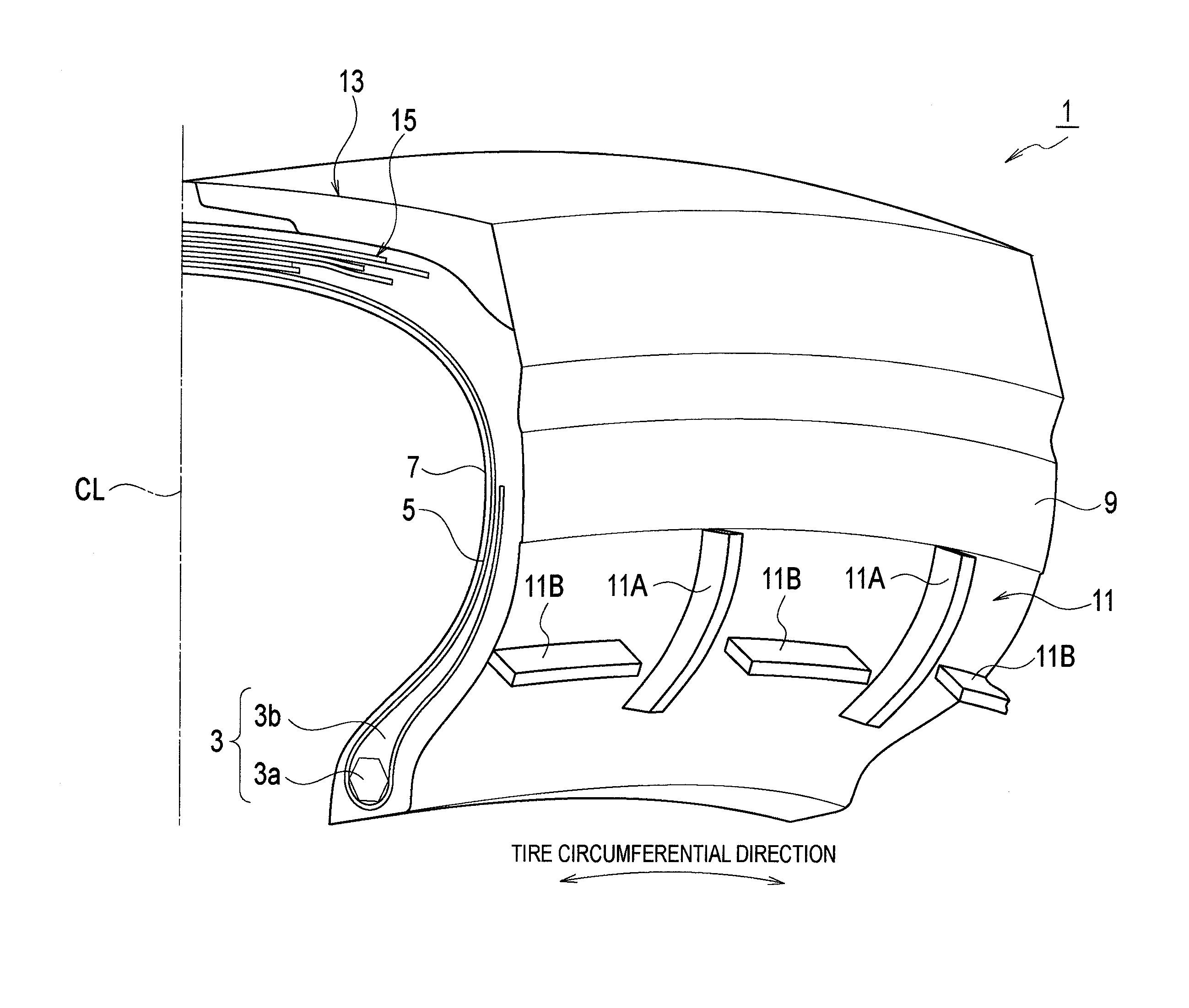
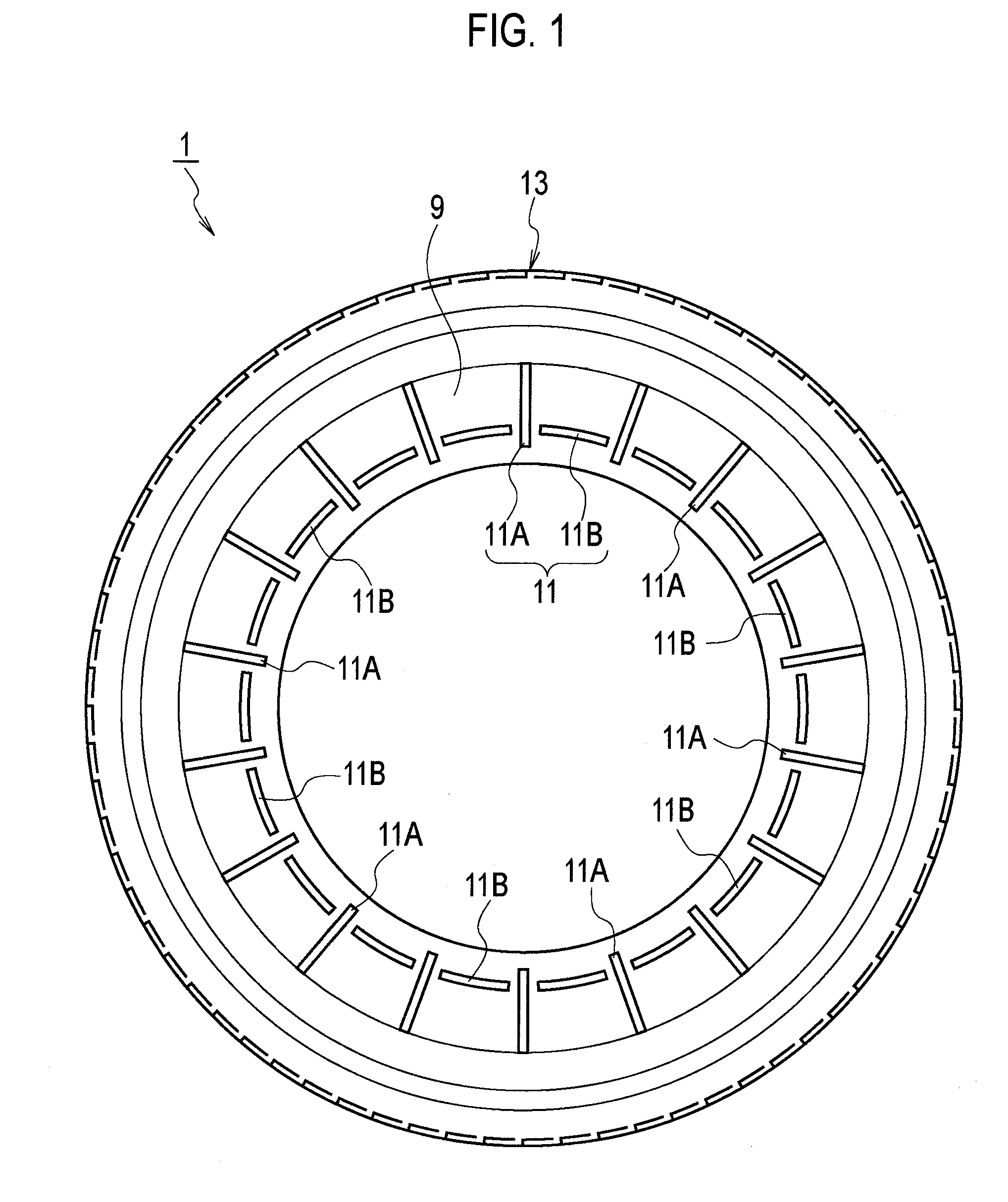
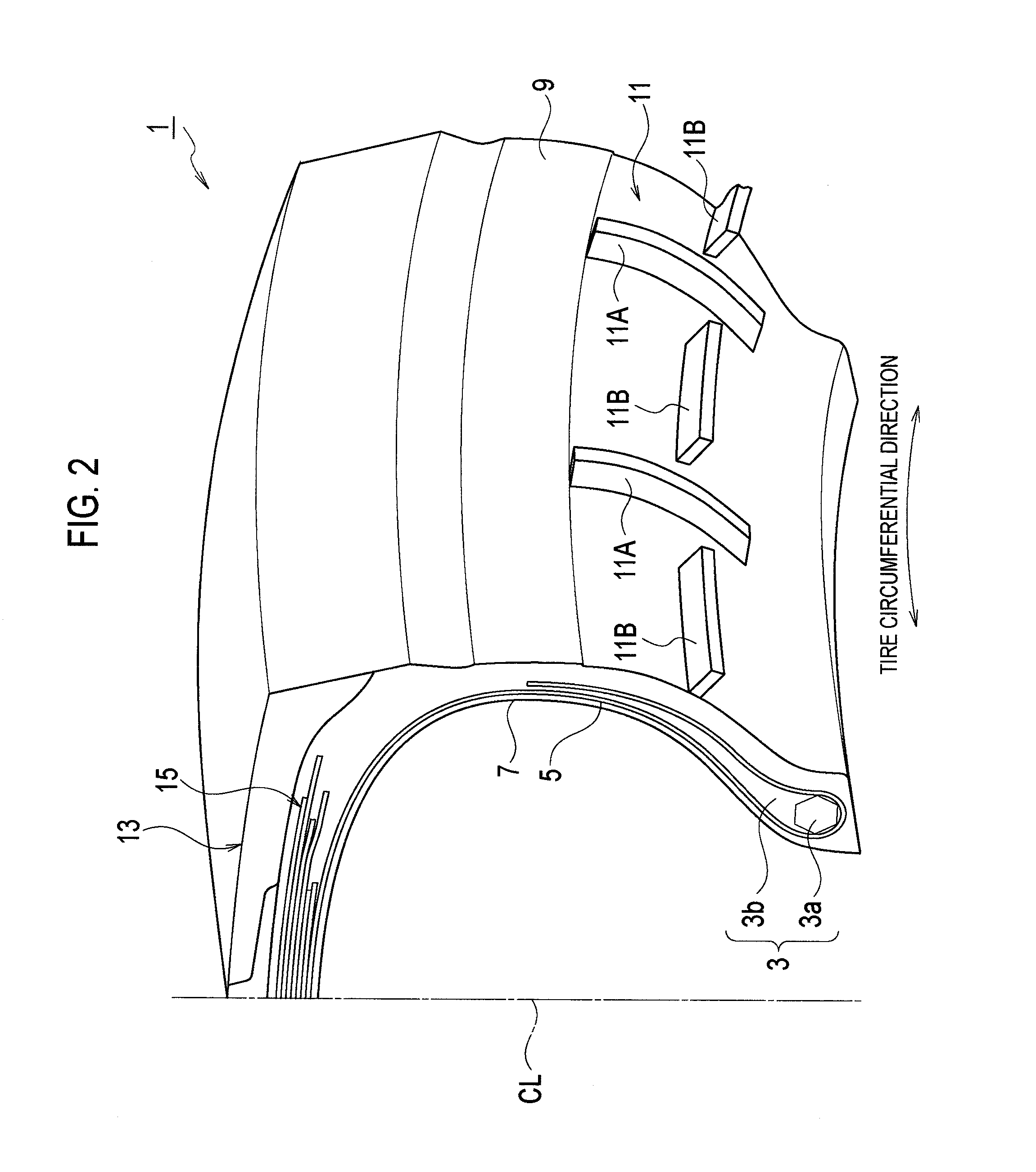
Provided is a pneumatic tire including at least a turbulent flow generation projection configured to generate a turbulent flow, the turbulent flow generation projection being arranged in a range from a maximum tire width position to an outside bead position, the maximum tire width position being a position on a tire surface with maximum tire width, and the outside bead position being a position on an outside of a bead portion in a tire radial direction, the bead portion configured to be in contact with a rim flange. The turbulent flow generation projection includes a radial projection extending along the tire radial direction, and a circumferential projection extending in an approximately circular arc shape along a tire circumferential direction.

Description

TECHNICAL FIELD[0001]The present invention relates to a pneumatic tire, and particularly, to a pneumatic tire provided with a turbulent flow generation projection for generating a turbulent flow at least in a portion of the tire surface.BACKGROUND ART[0002]In general, a rise of the tire temperature of a pneumatic tire is considered to be unfavorable from the viewpoint of durability because such rise may accelerate change over time such as deterioration of the material properties of the tire, or may cause breakage of its tread portion at the time of high speed traveling. Especially, for off-the-road radial tire (ORR) and truck / bus radial tire (TBR) for use under heavy load, and run-flat tire at the time of driving with a puncture (with 0 kPa internal pressure), reduction of the tire temperature in order to improve the durability of the tire has been a great challenge.[0003]For example, a pneumatic tire with the following configuration has been disclosed: the tire thickness is increas...

Claims


Application Information

Patent Timeline
Patent Type & Authority Applications(United States)
IPC IPC(8): B60C23/19
CPCB60C2200/06B60C13/02
Inventor KUROISHI, KAZUYA
Owner BRIDGESTONE CORP
Why Eureka
Try Eureka