
Case mounting structure, case, and case mounting method

a technology for mounting structures and cases, applied in rigid containers, manufacturing tools, transportation and packaging, etc., can solve the problems of increasing device costs and increasing the number of parts, and achieve the effect of strong mounting strength

Inactive Publication Date: 2011-01-27
NEC CORP
View PDF7 Cites 0 Cited by
  • Summary
  • Abstract
  • Description
  • Claims
  • Application Information

AI Technical Summary

Benefits of technology

[0020]According to the present invention, a screw to fix the cover is not necessary and it is possible to have strong mounting strength against shock generated at a time of falling.

Problems solved by technology

Since using a screw causes to increase number of parts, using a screw is a main factor to enlarge device size and to increase a device cost.

Method used


Image

  • Case mounting structure, case, and case mounting method
  • Case mounting structure, case, and case mounting method
  • Case mounting structure, case, and case mounting method

Examples


Embodiment Construction

[0059]First, an exemplary embodiment according to the case mounting structure and the case of the present invention will be described in the following.

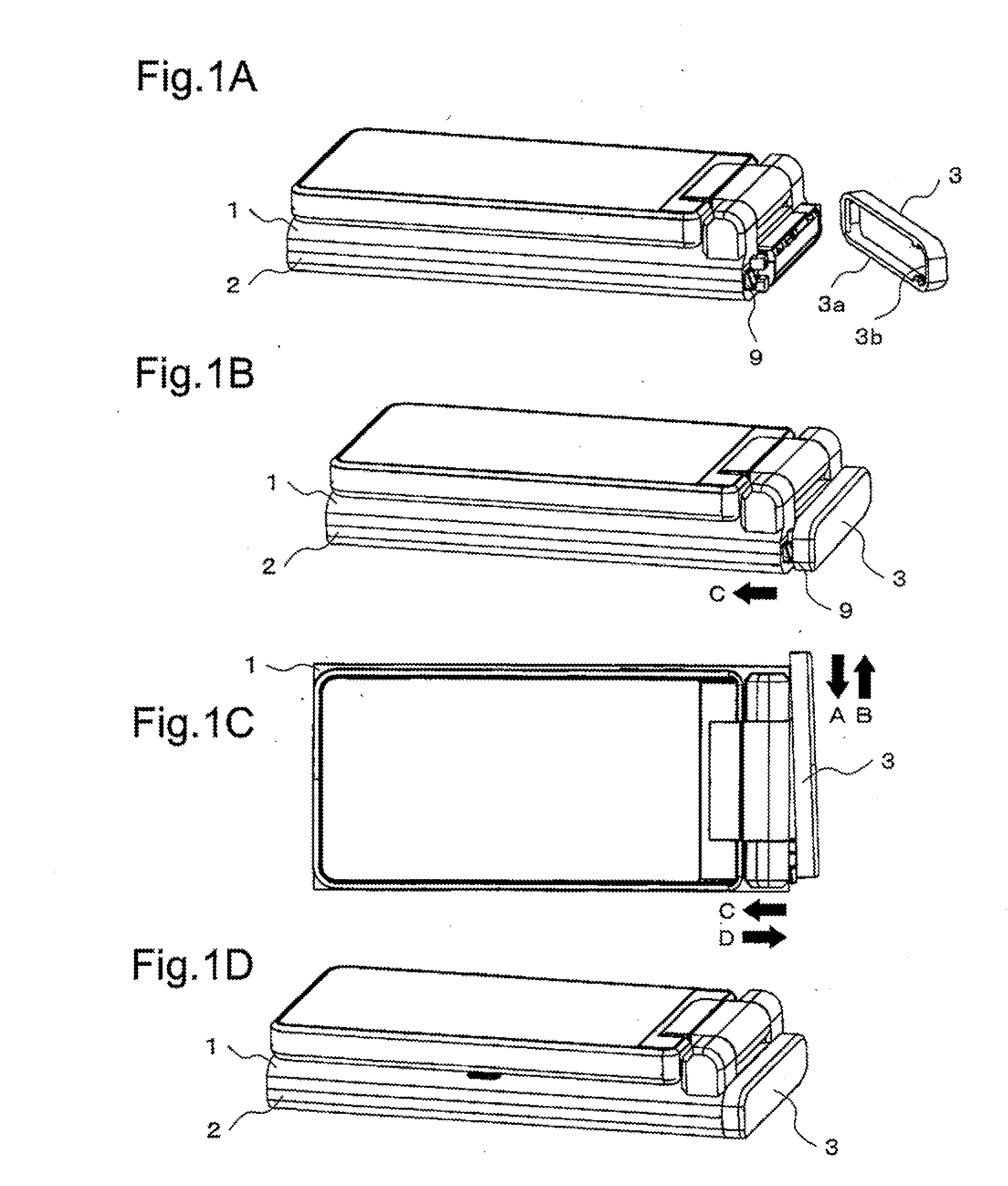
[0060]FIG. 1A, FIG. 1B, FIG. 1C and FIG. 1D show an example of a cover attaching process respectively on the basis of the case mounting structure according to the exemplary embodiment. FIG. 1A shows an example of the cover attaching process on the basis of the case mounting structure according to the exemplary embodiment. FIG. 1B, FIG. 1C and FIG. 1D show other state in the cover attaching process respectively.

[0061]The case mounting structure and the case according to the exemplary embodiment include a front case 1, a rear case 2, a cover 3 and a lock part 9. Further, the front case 1 and the rear case 2 can be called a case.

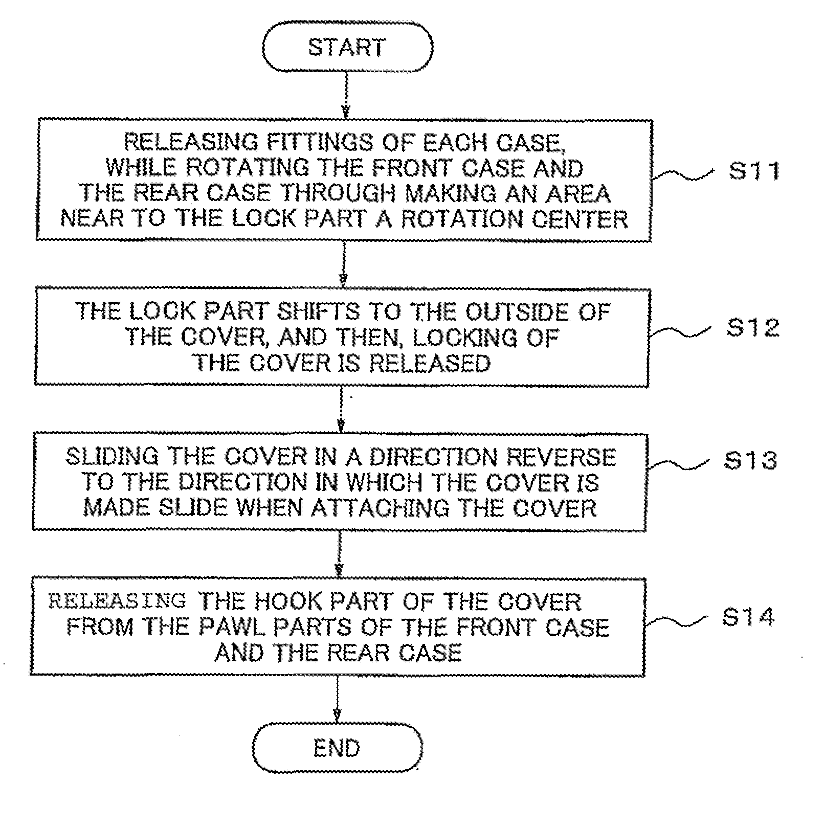
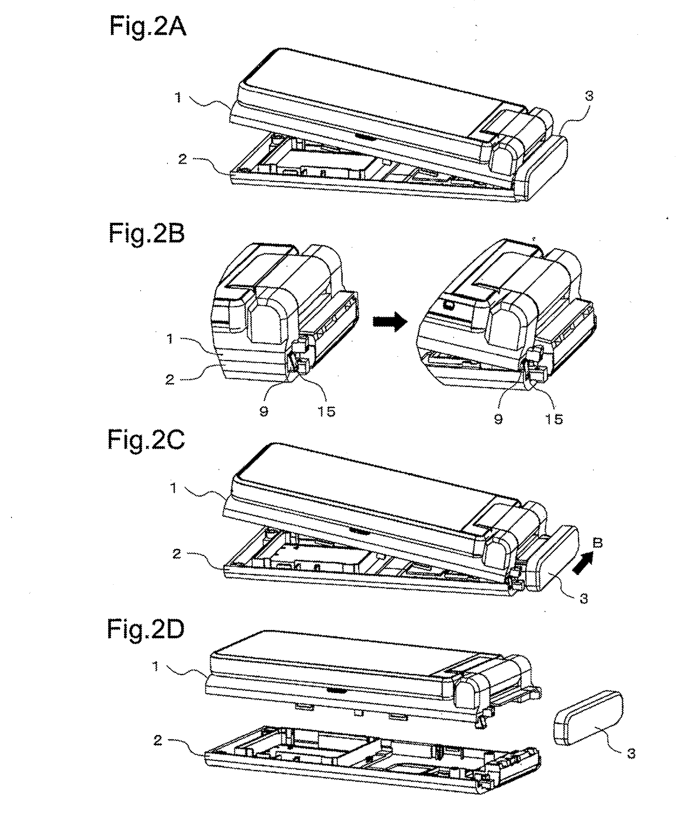
[0062]The rear case 2 can be joined to the front case 1. The cover 3 can be attached to the front case 1 and the rear case 2. The lock part 9 is arranged on one end part of the front case 1, and is deformed throu...


PUM

PropertyMeasurementUnit
angleaaaaaaaaaa
areaaaaaaaaaaa
timeaaaaaaaaaa

Abstract

An object of the present invention is to provide case mounting structure, a case and a case mounting method, which do not use a screw to fix the cover and has strong mounting strength against shock which is generated when the case falls.The case mounting structure according to the present invention includes a cover which can be attached to a case, and a lock part which is arranged on the case and locks the cover, wherein the lock part is deformed so as to prevent a movement for releasing lock when the cover is attached to the case.

Description

TECHNICAL FIELD[0001]The present invention relates to case mounting structure, a case and a case mounting method and particularly, relates to case mounting structure, a case and a case mounting method of a portable type electronic device.BACKGROUND ART[0002]In recent years, a portable type electronic device such as a cellular phone is composed of not only a front case and a rear case, but also another part (cover of case end part) in order to enhance the design property.[0003]At this time, a screw is often used to fix the cover of case end part (hereinafter, “cover” will be used.) for enhancing the shock resisting property. Since using a screw causes to increase number of parts, using a screw is a main factor to enlarge device size and to increase a device cost.[0004]It is still major proposition to enhance the design property of the portable electronic device and simultaneously, to secure the shock resisting property and to realize both of miniaturization and cost reduction of the ...

Claims


Application Information

Patent Timeline
Patent Type & Authority Applications(United States)
IPC IPC(8): B65D90/00B23P19/00
CPCY10T29/49826Y10T29/49817H04M1/0252H04M1/185
Inventor KUMAGAI, KEIICHIROU
Owner NEC CORP
Learn More