
Method for classifying a clutch unit

a technology of clutch unit and classifier, which is applied in the field of classifying a clutch unit, can solve the problems of large memory requirement, unfavorable adjustment of setting accuracy, damage to clutch components, etc., and achieve the effect of reducing the memory requirement, increasing the adaptation of the characteristic curve, and being easy to handl

Active Publication Date: 2011-01-20
MAGNA POWERTRAIN AG & CO KG
View PDF11 Cites 2 Cited by
  • Summary
  • Abstract
  • Description
  • Claims
  • Application Information

AI Technical Summary

Benefits of technology

[0017]According to the invention, it has been recognized that a clutch unit calibrated by means of the dynamic method has a higher setting accuracy in certain ranges of the clutch torque than a clutch unit calibrated by means of the static method, while in other ranges of the clutch torque, a clutch unit calibrated by means of the static method has a higher setting accuracy than a clutch unit calibrated by means of the dynamic method. If two separate value ranges of the clutch torque to be transmitted are now specified, and for each value range a calibration according to the method which is particularly suitable for said range is carried out, then it is possible overall to obtain an improved setting accuracy of the calibrated clutch unit. According to the invention, the two different calibration methods are thus advantageously combined to form an overall calibration method. Each of the calibration methods can be used for the range for which it yields the better setting accuracy results. As a result, this enables a more precise representation of the actual conditions by the characteristic curve.
[0021]At least two corrective values may be determined for one or both value ranges. This increases the accuracy of the characteristic curve adaptation.
[0023]The predefined characteristic curve—that is to say the abovementioned base characteristic curve—is preferably stored in a control device which is connected to the clutch unit, wherein the determined gradient adaptation value and the determined offset adaptation value are stored in a non-volatile memory which is assigned to the control device. The assignment may be realized for example by means of an electrical connection. Therefore, the predefined characteristic curve, which is the same for all clutch units of a certain type, is advantageously stored in the control device, such that the control devices can be manufactured uniformly, separately from the clutch units. The gradient adaptation value and the offset adaptation value which bear the individual calibration information are stored in a separate memory which, when the clutch unit is fully assembled, can be read out by the control device. Since said memory must only store individual adaptation values, it may be of correspondingly small design.
[0025]The gradient adaptation value and / or the offset adaptation value is preferably selected from a group of several predefined class values. In other words, it is possible for a plurality of possible classes of different gradient adaptation values and offset adaptation values to be specified, one of which is selected on the basis of the first and second corrective values. The memory requirement can be further reduced in this way.
[0027]It is also possible for more than two value ranges of the clutch torque to be transmitted to be specified, in order to thereby further increase the adaptation of the characteristic curve to the actual conditions.

Problems solved by technology

For this purpose, not only is a controlled engagement of the friction clutch required, but rather often also a relatively long period of operation with a precisely set clutch torque.
This however entails a high level of calculation expenditure and a large memory requirement.
Depending on the driving situation, it can be the case that both a characteristic curve adapted according to the dynamic process and also a characteristic curve adapted according to the static method do not sufficiently accurately represent the real setting behavior, which leads to undesired impairment of the setting accuracy.
In particular, in certain driving situations, for example during a starting process, it can be the case that inadmissibly high clutch torques are transmitted, which can result in damage to clutch components.

Method used


Image

  • Method for classifying a clutch unit
  • Method for classifying a clutch unit
  • Method for classifying a clutch unit

Examples


Embodiment Construction

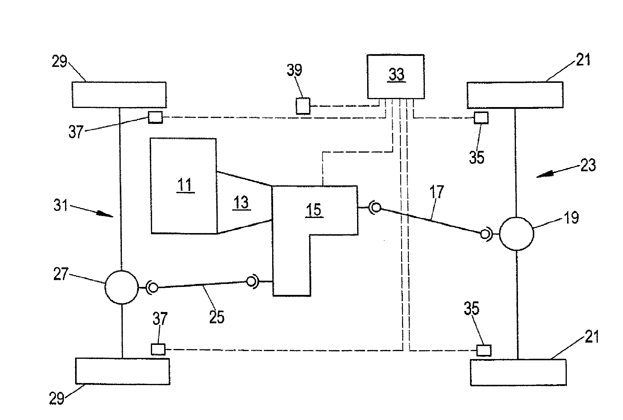
[0034]FIG. 1 schematically shows a drivetrain of a motor vehicle having switchable all-wheel drive. The drive torque generated by an internal combustion engine 11 is supplied via a main transmission 13 (manual shift transmission or automatic transmission) to a transfer box 15. A first output of the transfer box 15 is coupled via a cardan shaft 17 to a rear axle differential gear 19. The wheels 21 of the rear axle 23 are permanently driven in this way. The rear axle 23 therefore forms the primary axle of the vehicle. A second output of the transfer box 15 is coupled via a cardan shaft 25 to a front axle differential gear 27. In this way, a part of the drive torque of the internal combustion engine 11 can selectively be transmitted to the wheels 29 of the front axle 31. The front axle 31 thus forms the secondary axle of the vehicle.

[0035]FIG. 1 also shows a driving dynamics regulating unit 33. The latter is connected to wheel rotational speed sensors 35, 37 which are assigned to the w...


PUM


Abstract

A method is described for classifying a clutch unit for a drivetrain of a motor vehicle, wherein the clutch unit has at least one friction clutch for the controllable transmission of a torque from an input element to an output element and has an actuator for actuating the friction clutch. Here, the clutch unit is controlled on the basis of a predefined characteristic curve which describes a predefined dependency of the clutch torque to be transmitted on an actuator control variable.

Description

BACKGROUND OF THE INVENTION[0001]The present invention relates to a method for classifying a clutch unit for a drivetrain of a motor vehicle, wherein the clutch unit has at least one friction clutch for the controllable transmission of a torque from an input element to an output element and has an actuator for actuating the friction clutch, and wherein the clutch unit is controlled on the basis of a predefined characteristic curve which describes a predefined dependency of the clutch torque to be transmitted on an actuator control variable.[0002]A clutch unit of said type serves, for example in a transfer box of a motor vehicle with all-wheel drive, for the controllable transmission of a drive torque to a primary axle and / or a secondary axle of the motor vehicle. In a so-called “torque on demand” transfer box, the wheels of the primary axle are permanently driven, while a part of the drive torque can be selectively transmitted to the wheels of the secondary axle by means of said clu...

Claims


Application Information

Patent Timeline
IPC IPC(8): G06F19/00
CPCF16D48/06F16D2500/10425F16D2500/5116F16D2500/50248F16D2500/50236
Inventor BIANCALE, RAPHAELMAIER, GERNOTKIESSNER-HAIDEN, MARTINPARIGGER, MARTIN
Owner MAGNA POWERTRAIN AG & CO KG
Learn More