
Flat doppler probe and method of the same

a doppler probe and flat technology, applied in the field of ultrasonic probes, can solve the problems of less effective examining air-filled organs or bones, difficult to obtain doppler signals on patients with vascular disease, and the crystal of the doppler is not positioned at an optimal angle for ease of us

Inactive Publication Date: 2011-01-20
NATUS MEDICAL
View PDF11 Cites 75 Cited by
  • Summary
  • Abstract
  • Description
  • Claims
  • Application Information

AI Technical Summary

Benefits of technology

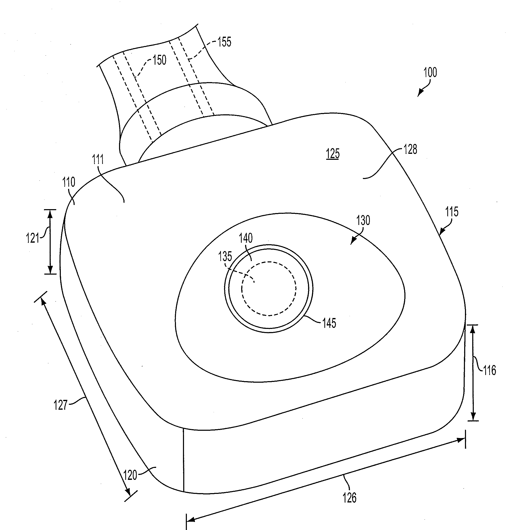
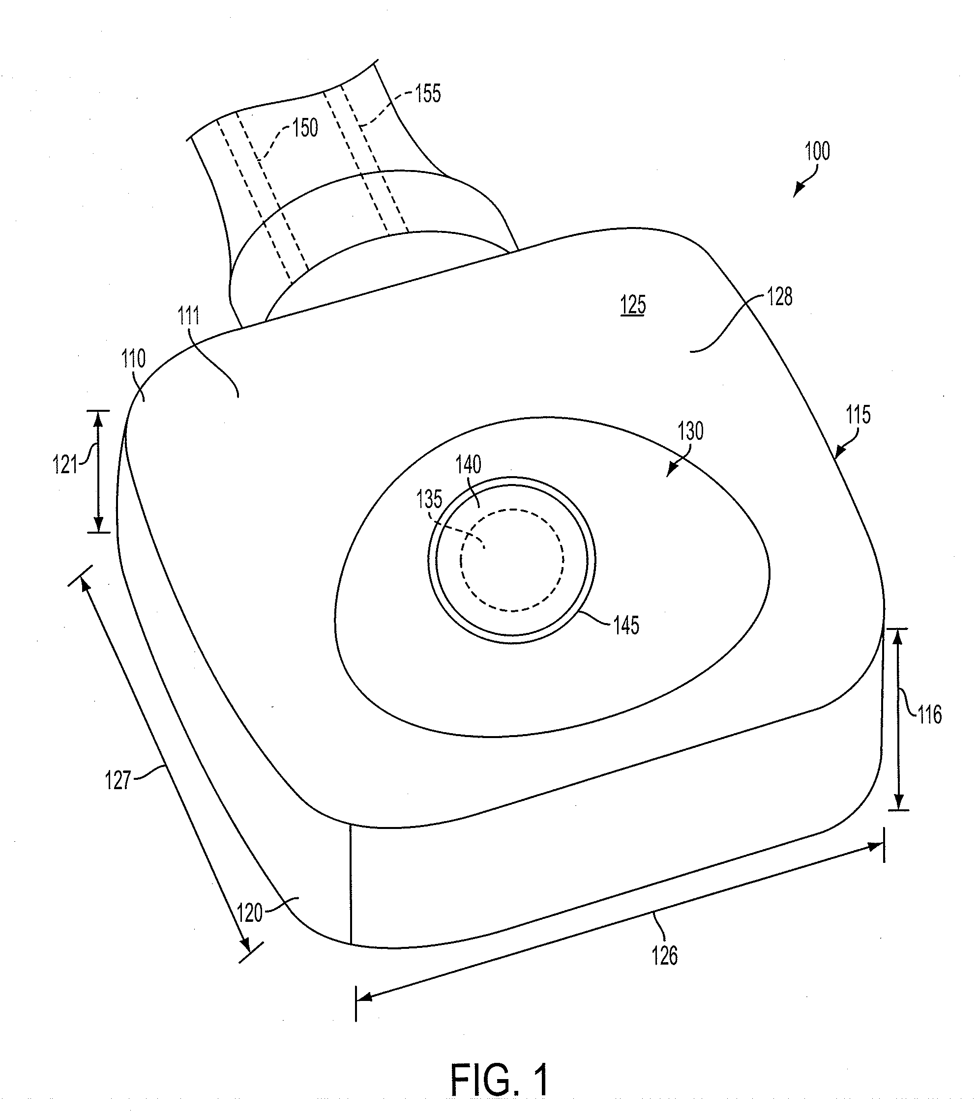
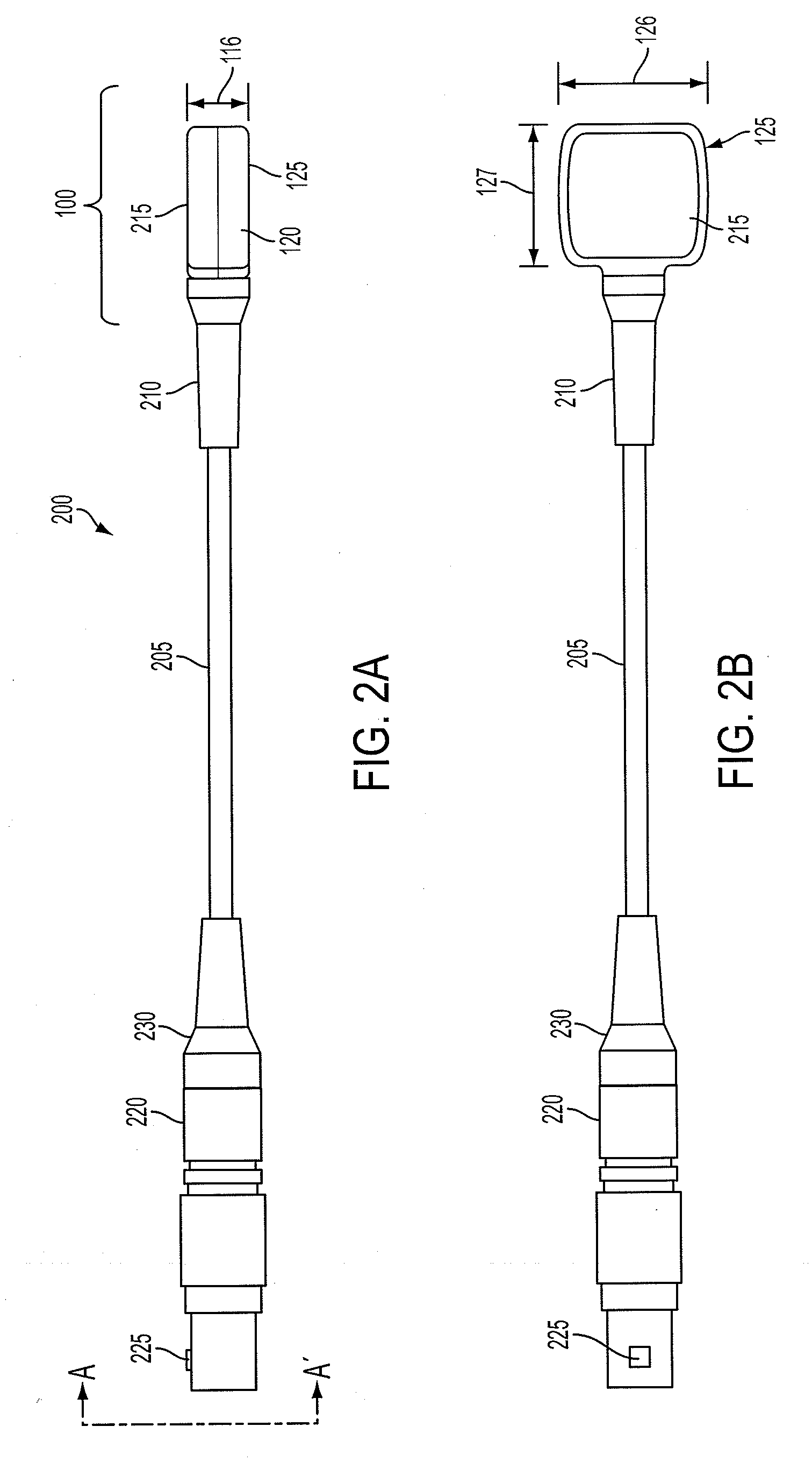
The present invention provides a flat ultrasound probe with an ultrasound crystal at an optimum angle for ease of use and allowing enough gel to be applied to aid in receiving the ultrasound signals. The flat ultrasound probe has a housing with sidewalls, a bottom surface for contacting an external surface of a patient during operation of the probe, and a flat portion in the bottom surface for containing a transmission material on the outer surface of the housing for aiding in transmission of ultrasound signals. The invention also includes a method of providing an ultrasound Doppler spectrum using a flat ultrasound probe, and a flat ultrasound probe with means for housing and a recessed bottom surface for containing a means for aiding transmission of ultrasound signals. The technical effects of the invention include improved ultrasound imaging and easier use of the ultrasound probe.

Problems solved by technology

Sonography allows for the production of images of organs that are soft or filled with fluid, but it is less effective for examining air-filled organs or bones.
For example, it is typically more difficult to obtain Doppler signals on patients with vascular disease because of their decreased blood flow.
A drawback of conventional flat Doppler probes is that the Doppler crystal is not positioned at an optimum angle for ease of use (sensitivity for signal location).
In addition, the flat surface does not leave room for enough gel to be applied to aid in receiving the Doppler signals.

Method used


Image

  • Flat doppler probe and method of the same
  • Flat doppler probe and method of the same
  • Flat doppler probe and method of the same

Examples


Embodiment Construction

[0023]In the following detailed description, reference is made to the accompanying drawings, which form a part hereof and show by way of illustration specific embodiments in which the invention may be practiced. These embodiments are described in sufficient detail to enable those skilled in the art to practice them, and it is to be understood that other embodiments may be utilized, and that structural, logical, processing, and electrical changes may be made. It should be appreciated that any list of materials or arrangements of elements is for example purposes only and is by no means intended to be exhaustive. The progression of processing steps described is an example; however, the sequence of steps is not limited to that set forth herein and may be changed as is known in the art, with the exception of steps necessarily occurring in a certain order.

[0024]The invention will now be described with reference to the drawing figures in which like reference numerals refer to like parts th...


PUM


Abstract

A flat ultrasound probe includes a housing having sidewalls, each having a height, a bottom surface for contacting an external surface of a patient during operation of the probe, the bottom surface having a width larger than the height of the sidewalls and a flat portion, and a recession in the bottom surface for containing a transmission material on an outer surface of the housing for aiding in transmission of ultrasound signals, the recession being rounded on all sides where the recession contacts the flat portion of the bottom surface.

Description

FIELD OF THE INVENTION[0001]The present invention relates to ultrasound probes, that are generally flat probes. More specifically, the present invention relates specifically to Doppler probes.BACKGROUND OF THE INVENTION[0002]Ultrasound scanning, also commonly referred to as sonography, is oftentimes used to view and / or examine tissues and organs inside the body. It employs high-frequency sound waves, which cannot be heard by humans, to produce images of structures inside the body. Sonography allows for the production of images of organs that are soft or filled with fluid, but it is less effective for examining air-filled organs or bones.[0003]One of the most common uses of sonography is to evaluate the progress of the fetus during pregnancy. Another common use of sonography is to view and to determine whether a lump or mass is a cyst. Moreover, sonography is utilized to look at the size and shape of abdominal and pelvic organs, to detect gallstones, and to detect blood clots in the ...

Claims


Application Information

Patent Timeline
Patent Type & Authority Applications(United States)
IPC IPC(8): A61B8/13
CPCA61B8/488A61B8/4455G01N29/24A61B8/00
Inventor HEASTY, RAYPOOLE, TONYZEISLER, CHRISTINA
Owner NATUS MEDICAL
Learn More