
UWB transmitter

a transmitter and ultrawideband technology, applied in the field of ultrawideband communication, can solve the problem that uwb signals are more difficult to detect than narrowband (essentially single frequency) signals

Inactive Publication Date: 2011-01-20
LAWRENCE LIVERMORE NAT SECURITY LLC
View PDF5 Cites 8 Cited by
  • Summary
  • Abstract
  • Description
  • Claims
  • Application Information

AI Technical Summary

Problems solved by technology

UWB signals are more difficult to detect than narrowband (essentially single frequency) signals.

Method used


Image

  • UWB transmitter
  • UWB transmitter
  • UWB transmitter

Examples


Embodiment Construction

[0026]Referring more specifically to the drawings, for illustrative purposes the present invention is embodied in the apparatus generally shown in FIG. 1 through FIG. 4. It will be appreciated that the apparatus may vary as to configuration and as to details of the parts, without departing from the basic concepts as disclosed herein.

[0027]UWB Transmitter

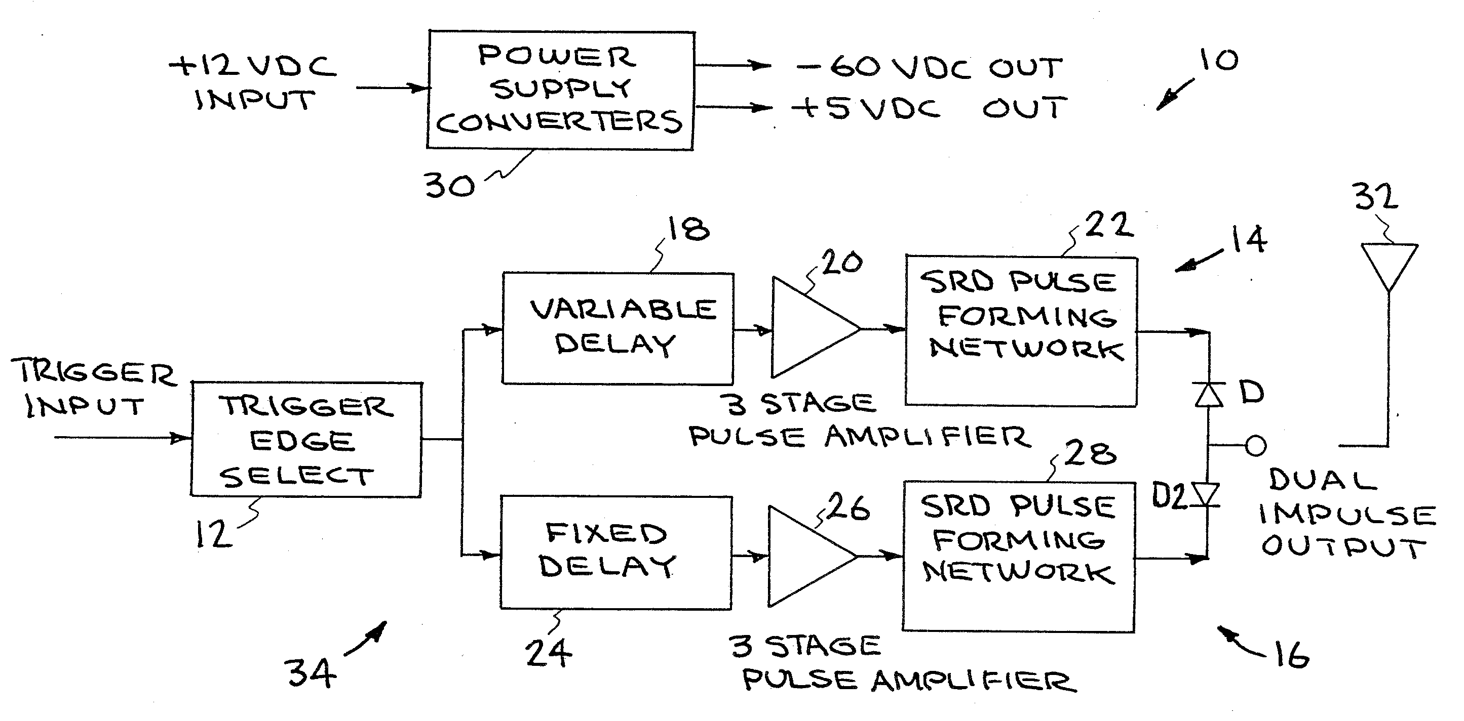
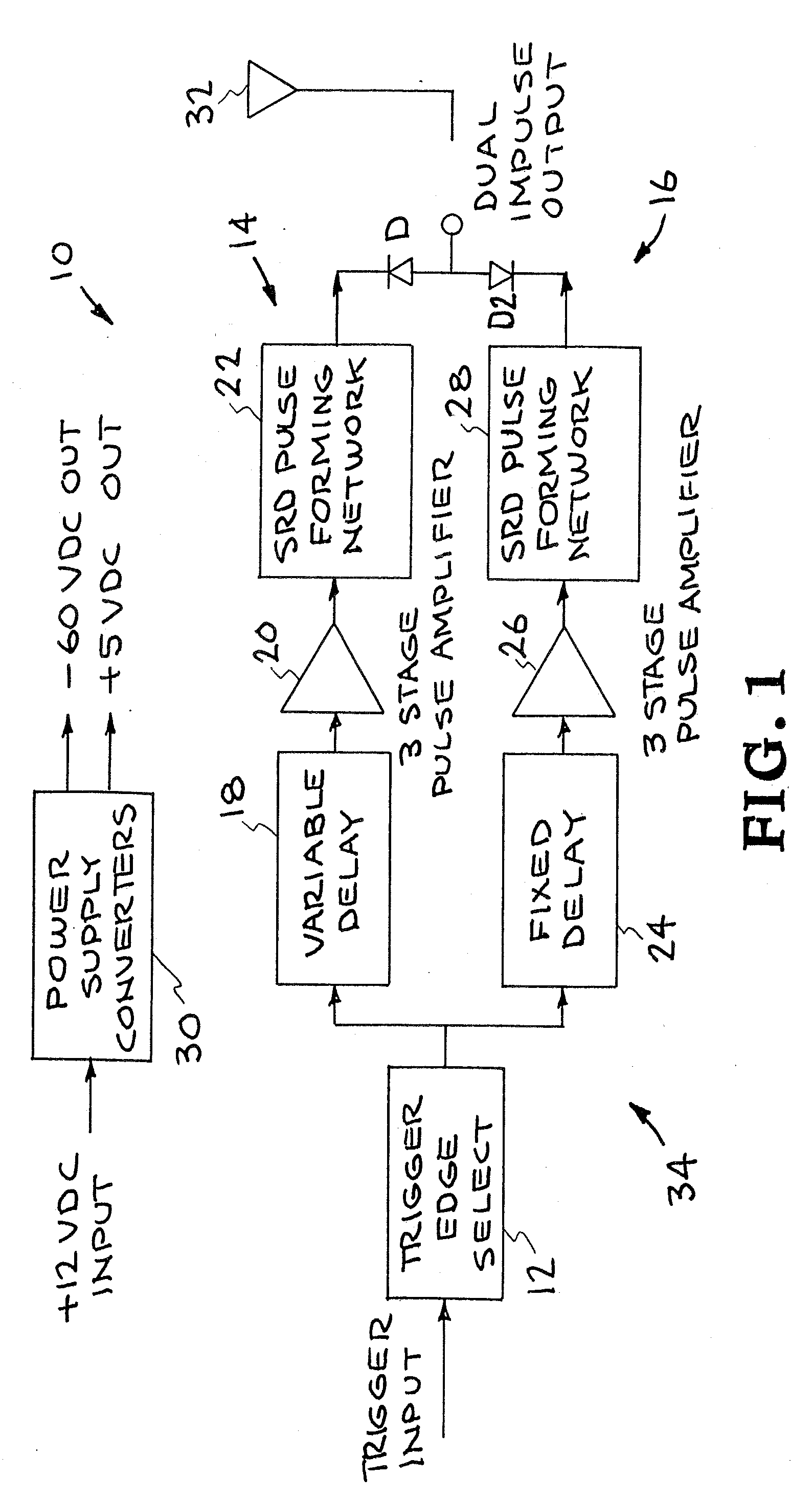
[0028]The invention includes a dual impulse transmitter that is used in ultra-wideband (UWB) communication systems. The circuit generates dual impulses from a single trigger event. Each impulse has a peak of about 50 V.

[0029]One technique in ultra-wideband (UWB) communications involves a delay and multiply receiver topology. This receiver technique requires two input signals that can be delayed and overlaid on top of one another to detect a valid signal. This requires a transmitted signal that is comprised of two pulses that are delayed by a fixed, stable and repeatable amount of time.

[0030]The transmitter of the invention generates ...


PUM


Abstract

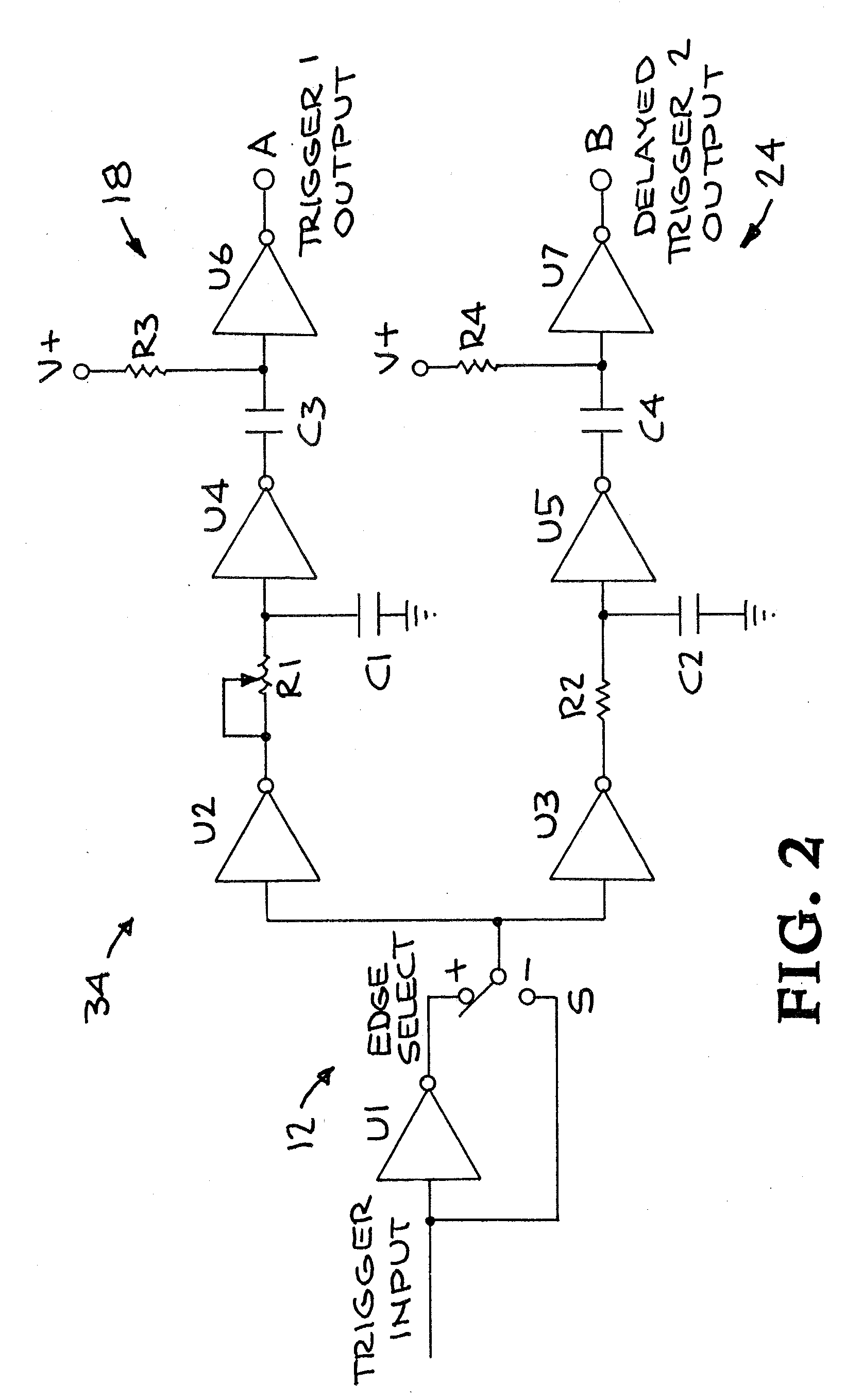
An ultra-wideband (UWB) dual impulse transmitter is made up of a trigger edge selection circuit actuated by a single trigger input pulse; a first step recovery diode (SRD) based pulser connected to the trigger edge selection circuit to generate a first impulse output; and a second step recovery diode (SRD) based pulser connected to the trigger edge selection circuit in parallel to the first pulser to generate a second impulse output having a selected delay from the first impulse output.

Description

RELATED APPLICATIONS[0001]This application claims priority to U.S. Provisional No. 61 / 138,047, titled “Enhanced UWB Impulse Generator,” filed Dec. 16, 2008 and incorporated herein by reference.GOVERNMENT RIGHTS[0002]The United States Government has rights in this invention pursuant to Contract No. DE-AC52-07NA27344 between the United States Department of Energy and Lawrence Livermore National Security, LLC.BACKGROUND OF THE INVENTION[0003]1. Field of the Invention[0004]This invention pertains generally to ultra-wideband communications, and more particularly to ultra-wideband (UWB) transmitters.[0005]2. Description of Related Art[0006]Ultra-wideband (UWB) wireless communication is based on the transmission of data in extremely short (50-1000 ps) pulses spread out over a broad range or bandwidth (typically several GHz) of the electromagnetic spectrum. Large data bursts, e.g. hundreds of Gb / s, are possible because the data are carried simultaneously at a wide range of frequencies acros...

Claims


Application Information

Patent Timeline
IPC IPC(8): H04B1/707
CPCH04B1/7174
Inventor DALLUM, GREGORY E.PRATT, GARTH C.HAUGEN, PETER C.ROMERO, CARLOS E.
Owner LAWRENCE LIVERMORE NAT SECURITY LLC
Learn More