Knee Joint Including Manual Lock Mechanism and Artificial Thigh

a lock mechanism and knee joint technology, applied in the field of knee joint including manual lock mechanism and artificial thigh, can solve problems such as ineffective application, and achieve the effects of simple structure, excellent appearance of artificial thigh, and effective movement of knee join

Active Publication Date: 2011-01-13
NABLESCO CORP
View PDF3 Cites 10 Cited by
  • Summary
  • Abstract
  • Description
  • Claims
  • Application Information

AI Technical Summary

Benefits of technology

[0014]It is, therefore, an object of the present invention to provide a technology for achieving a simple structure of a manual lock mechanism capable of selectively switching over a locked condition and an unlocked condition at walk and achieving a size reduction of a knee joint and an artificial leg including the manual lock mechanism just mentioned.
[0015]Another object of the present invention is to provide a technology in which the appearance is excellent and operability for switching a manual lock mechanism is enhanced.
[0017]The inventors of the present invention paid attention to that the coupling means for swingably coupling the upper and lower members includes the oscillating shaft, and thought that a locked condition can be obtained by restricting the movement of the oscillating shaft. The oscillating shaft is essentially required for a knee joint and an artificial leg. By using the oscillating shaft as one of the component elements of the manual lock mechanism, the inventors aim at a simple structure of the manual lock mechanism.
[0021](C) a first end part of the lock member in the longitudinal direction is in face-to-face contact with the irregular part in the locked condition so that the upper and lower member prevent the knee from bending.
[0023]As a coupling means for swingably coupling the upper and lower members, there is a single axis where the center of oscillation is constant or a multi-axis where the center of oscillation is changed in accordance with the oscillating motion. With one having a single axis, movement of only one single-axis is restricted and with one having a multi-axis, movement of one of the plural oscillating shafts is restricted. Since only one single-axis is located at an upper part of the knee joint, the wearer of the artificial leg including this knee joint can operate the outer-side second end part (i.e., the manual operating part) opposite to the inner-side first end part facing the single-axis by himself and can easily switch over to the locked condition or the unlocked condition in accordance with necessity. With the multi-axis including the plural oscillating shafts, the oscillating shaft located at an upper part of the knee joint is restricted so that the same switching-over operation can be performed as in the single-axis. Therefore, the oscillating shaft located at an upper part of the knee joint is preferably restricted, and in that case, the lock member is most preferably supported on the socket attaching part having a sufficient mechanical strength.
[0027]This type knee joint and an artificial leg including the same is preferably provided with a resistance force (or a drag) generating means for generating a resistance force against bending or extending of the knee by the knee joint in order to effectively performing the movement by the knee joint. Since the manual lock mechanism of the present invention has a simple structure and requires only a small space, no difficulty is encountered with the employment of such resistance force generating means. The resistance force generating means may be one of a hydraulic cylinder, a spring cylinder and a pneumatic cylinder. In the artificial thigh equipped with the resistance force generating means in addition to the manual lock mechanism, the manual lock mechanism and the resistance force generating means are located at an inner side of the contour of the knee joint. Owing to this arrangement, a size reduction and an excellent appearance of the artificial thigh can be achieved.

Problems solved by technology

However, since such a technology for preventing knee bending uses the wearer's load, it cannot be effectively applied, for example, to a case where the wearer walks on a snow-covered road or an uneven ground.

Method used


Image

  • Knee Joint Including Manual Lock Mechanism and Artificial Thigh
  • Knee Joint Including Manual Lock Mechanism and Artificial Thigh
  • Knee Joint Including Manual Lock Mechanism and Artificial Thigh

Examples


Embodiment Construction

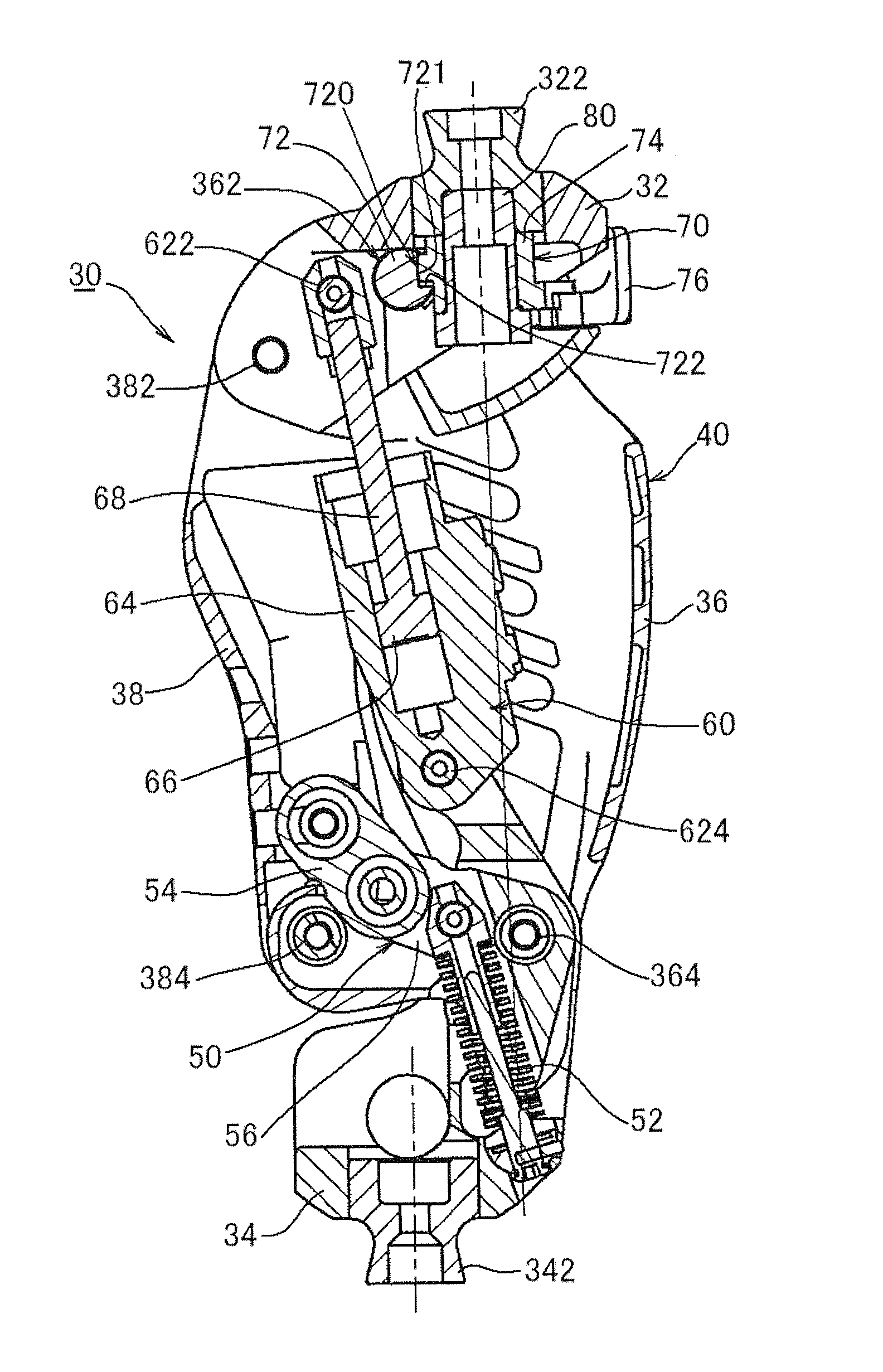
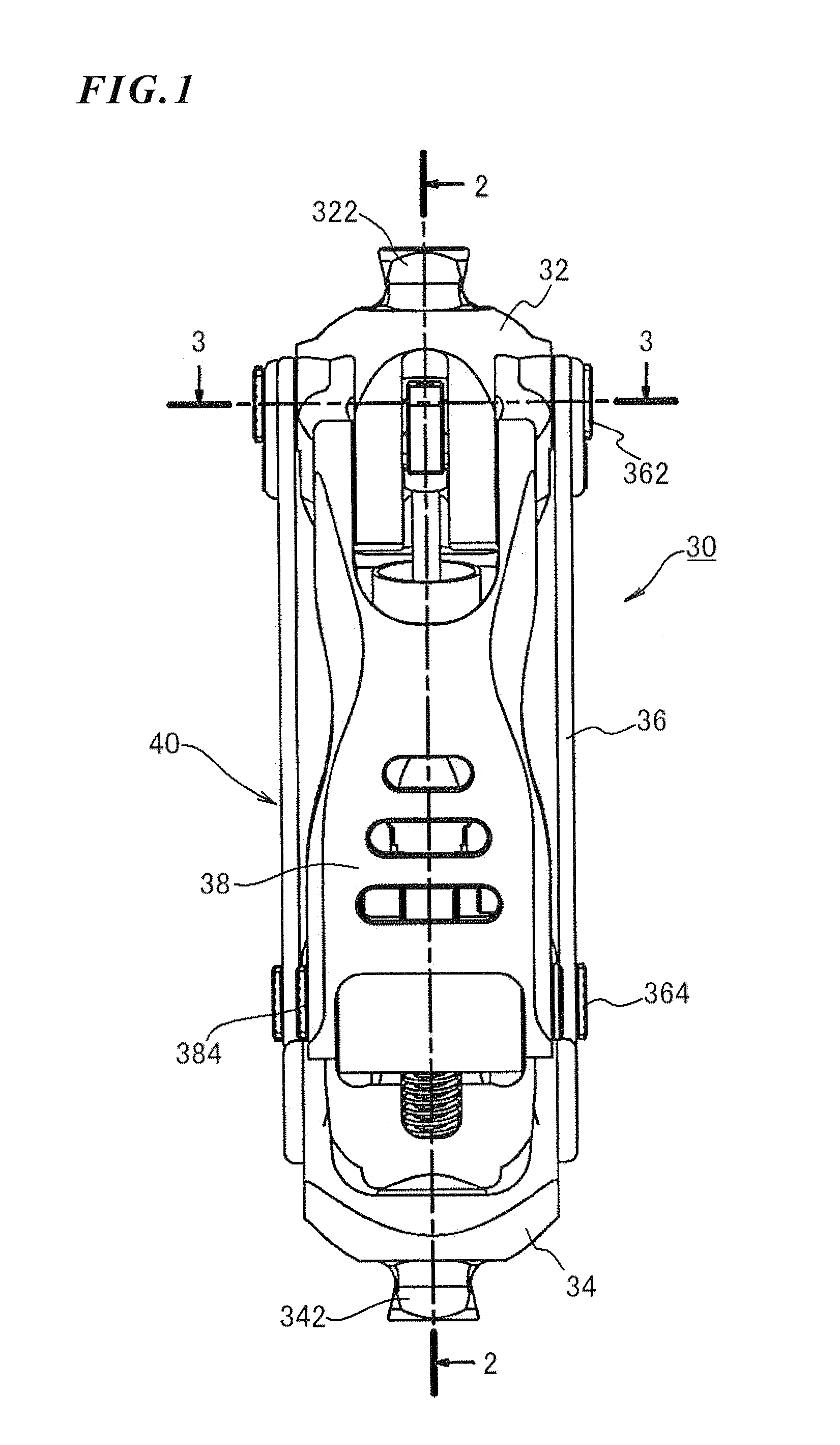
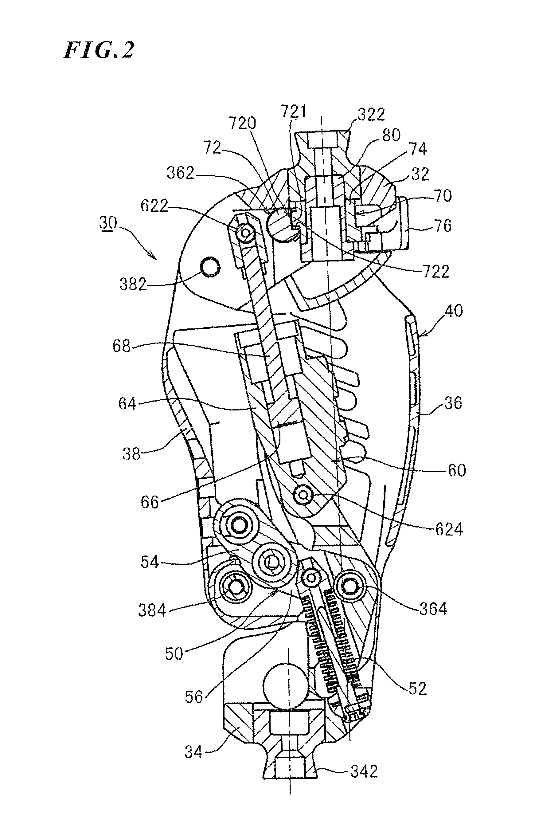
[0066]FIGS. 1 through 3 show a first embodiment in which the present invention is applied to a multi-axis knee joint. A multi-axis knee joint 30 of the first embodiment comprises an upper member 32 located at an upper side of the knee and a lower member 34 located at a lower side of the knee and swingably coupled to the upper member 32 to enable the knee to bend. The upper member 32 integrally supports an alignment block 322 on an upper center part thereof. The alignment block 322 is a part to which a socket, not shown, is attached and supports the artificial leg wearer's load through the thigh inserted in the socket. On the other hand, another alignment block 342 is also disposed at a lower center part of the lower member 34. This alignment block 342 is a part to which a member for supporting a foot part is attached. Therefore, the knee joint 30 constitutes a main part of the artificial thigh.

[0067]The multi-axis coupling means 40 swingably couples the upper and lower members 32 an...


PUM


Abstract

The disclosure relates to a technology of a manual lock mechanism for manually switching over the oscillating motion of an upper member and a lower member at a knee joint between a locked condition and an unlocked condition. More particularly, the disclosure aims at a simple structure of the manual lock mechanism and a size reduction of the knee joint or an artificial leg including the manual lock mechanism. For these purposes, one of oscillating shafts for swingingly coupling the upper and lower members is regulated. Therefore, the manual lock mechanism includes an oscillating shaft including an irregular part and a lock member for regulating the movement of the oscillating shaft. The lock member can be switched over between a locked condition where the lock member is in contact with the irregular part of the oscillating shaft and the unlocked condition where it is separate from the irregular part. When the lock member is in the locked condition, force from the oscillating shaft is applied as compression load in the longitudinal direction of the lock member.

Description

[0001]This invention relates to a knee joint capable of manually switching over an upper member located at an upper side of the knee and a lower member located at a lower side of the knee between an unlocked condition where the upper and lower members are swingable and a locked condition where they are unswingable when the knee is in its extended condition and an artificial thigh including the knee joint. More particularly, the invention relates to a technology for effectively achieving a size reduction of a manual lock mechanism for switching over the upper and lower members between the unlocked condition and the locked condition.BACKGROUND ART[0002]The knee joint functions as a knee capable of swinging an upper member and a lower member. One representative example of an artificial leg including such a knee joint is an artificial thigh (or an above knee prosthesis). The artificial leg including the knee joint normally comprises a resistance force (or a drag) generating means, such ...

Claims


Application Information

Patent Timeline
Patent Type & Authority Applications(United States)
IPC IPC(8): A61F2/78A61F2/64
CPCA61F2/642A61F2/68A61F2002/5072A61F2002/748A61F2002/745A61F2002/747A61F2002/6854A61F2/74A61F2/748
Inventor OKUDA, MASAHIKONAKAYA, YOSHIAKI
Owner NABLESCO CORP
Why Eureka
Try Eureka