
Ophthalmic apparatus

Inactive Publication Date: 2011-01-13
CANON KK
View PDF6 Cites 7 Cited by
  • Summary
  • Abstract
  • Description
  • Claims
  • Application Information

AI Technical Summary

Benefits of technology

[0009]The present invention is directed to an ophthalmic apparatus capable of detecting an appropriate working distance from a subject's eye and successfully capturing an image of the subject's eye.
[0011]Based on the ophthalmic apparatus according to the present invention, by analyzing the size of the blur of each positioning index image, an appropriate direction in moving the apparatus body part relative to the subject's eye can be detected, and an image of the subject's eye can be successfully captured without undesired light such as flare and ghost.

Problems solved by technology

However, neither of the fundus cameras can determine whether the fundus camera is positioned close to or far from the subject's eye with respect to an appropriate alignment position.
Namely, neither of the fundus cameras can accurately determine the working distance.
However, movement of the fundus camera in the opposite direction will result in a needless operation.

Method used


Image

  • Ophthalmic apparatus
  • Ophthalmic apparatus
  • Ophthalmic apparatus

Examples


Embodiment Construction

[0027]Various exemplary embodiments, features, and aspects of the invention will be described in detail below with reference to the drawings.

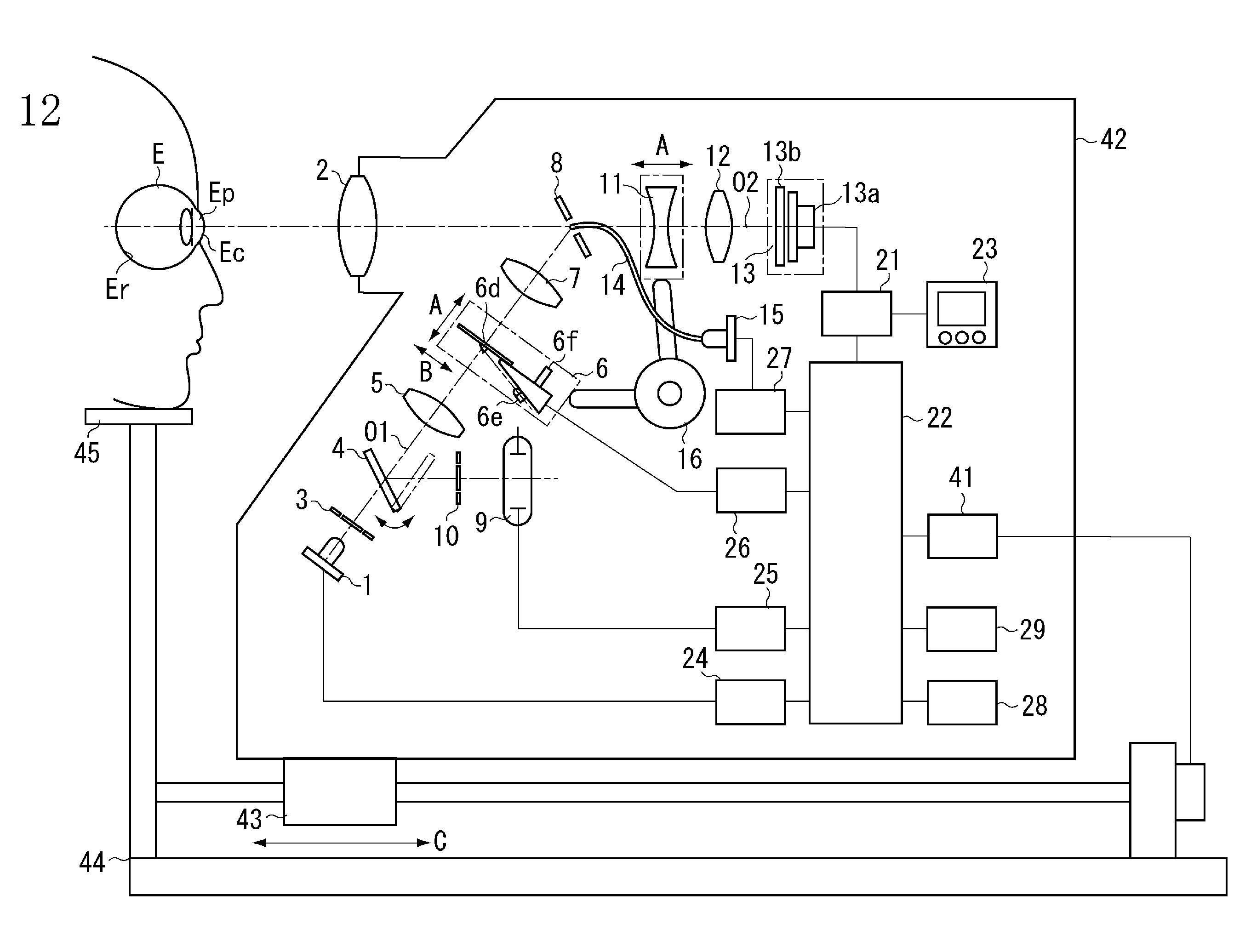
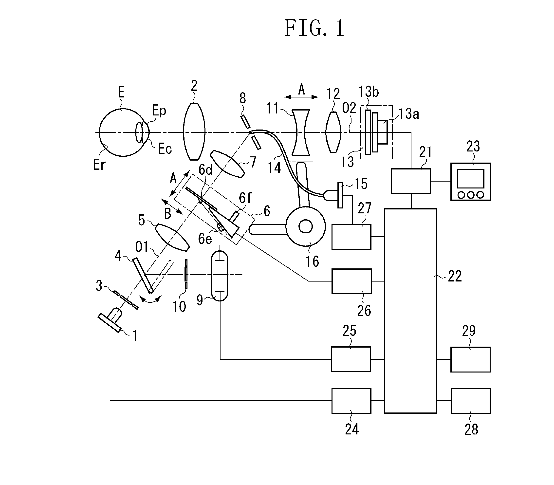
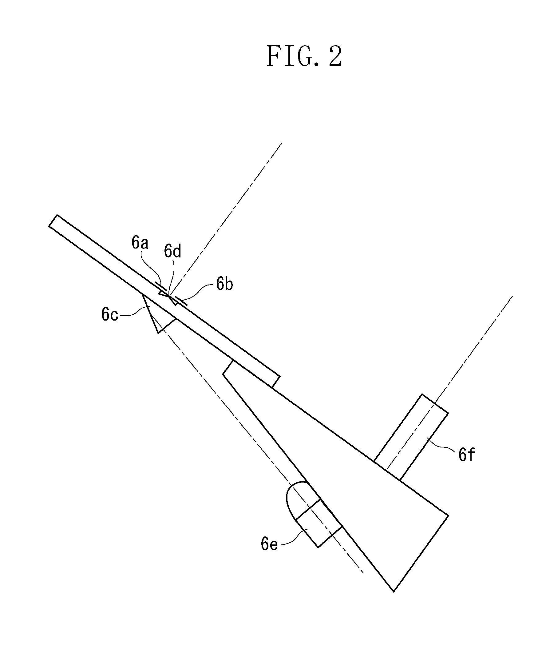
[0028]FIG. 1 illustrates a configuration of a fundus camera as an ophthalmic apparatus according to a first exemplary embodiment. The fundus camera includes an illumination optical system having an optical path O1 that runs from an observation light source 1 to an objective lens 2 facing a subject's eye E. The illumination optical system includes a diaphragm 3, a quick-return mirror 4, a relay lens 5, a focus index projection unit 6, a relay lens 7, and a perforated mirror 8 sequentially arranged in the optical path O1. When an operator observes a fundus, the quick-return mirror 4 retracts from the optical path O1 to a position indicated by a dashed line in FIG. 1. When the operator captures an image of the fundus, the quick-return mirror 4 is inserted to the optical path O1 in a position indicated by a solid line. The fundus camera further inc...


PUM


Abstract

When the fundus camera is positioned on the same side as the subject's eye relative to an appropriate position (front-focus state), the positioning index light source turned on in blue produces most-focused positioning index images. The positioning index light sources become more blurred in order of green and red. When the camera is positioned on the opposite side of the subject's eye relative to the appropriate position (rear-focus state), the positioning index light source turned on in red produces most-focused images. The positioning index light sources become more blurred in order of green and blue. Based on a degree of the blur of the individual positioning index images in red, green, and blue reflected by the cornea of the subject's eye, the calculation unit calculates whether to move the camera body closer to or farther away from the subject's eye and allows the display unit to display the information.

Description

BACKGROUND OF THE INVENTION[0001]1. Field of the Invention[0002]The present invention relates to an ophthalmic apparatus capturing an image of or measuring a subject's eye.[0003]2. Description of the Related Art[0004]Japanese Patent Application Publication No. 62-34530 discusses a fundus camera projecting an alignment index on a cornea of a subject's eye and obtaining a reflected image from the cornea as an alignment image. According to this technique, whether the fundus camera is in an appropriate alignment position is determined based on the focus status of the alignment image.[0005]Japanese Patent Application Publication No. 7-31590 also discusses a fundus camera projecting an alignment index on a cornea of a subject's eye and obtaining a reflected image from the cornea as an alignment image. According to this technique, whether the fundus camera is in an appropriate alignment position is determined based on separation or agreement of the alignment image.[0006]Since the above fun...

Claims


Application Information

Patent Timeline
IPC IPC(8): A61B3/15
CPCA61B3/12A61B3/14A61B3/1225A61B3/0008A61B3/152
Inventor ONO, SHIGEAKISHIKAUMI, MASAOSEKIGUCHI, KYOJIUCHIDA, KOJI
Owner CANON KK
Learn More