
Imaging optical system and imaging apparatus

a technology of applied in the field of imaging optical systems and imaging apparatuses, can solve the problems of difficult white balance adjustment under temperature conditions ranging from 20° c. to 80° c., and achieve the effects of high stability, desirable optical performance and surface precision

Inactive Publication Date: 2011-01-13
SONY CORP
View PDF3 Cites 11 Cited by
  • Summary
  • Abstract
  • Description
  • Claims
  • Application Information

AI Technical Summary

Benefits of technology

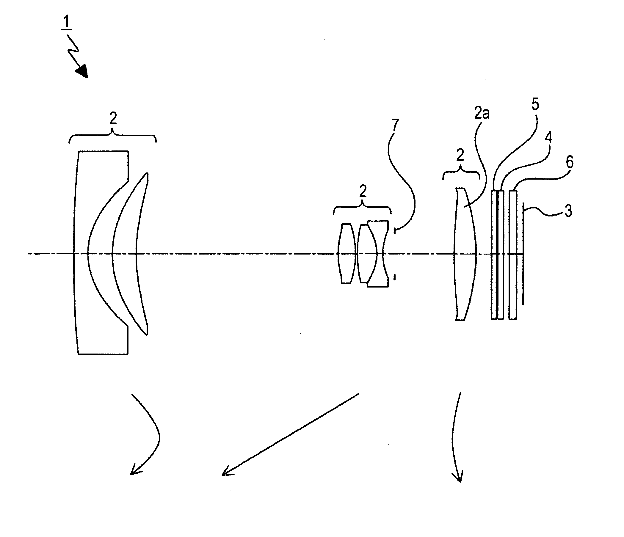
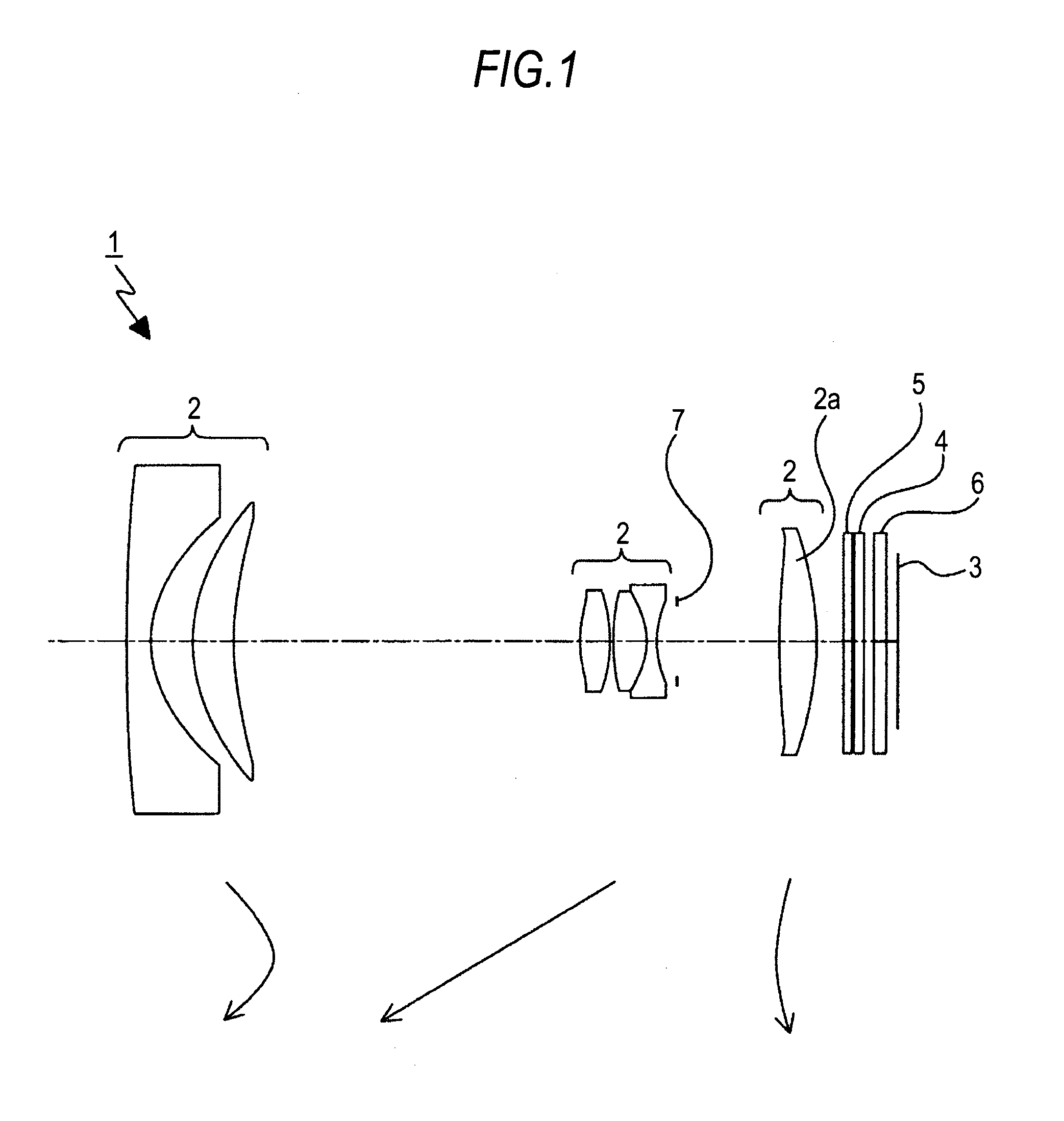
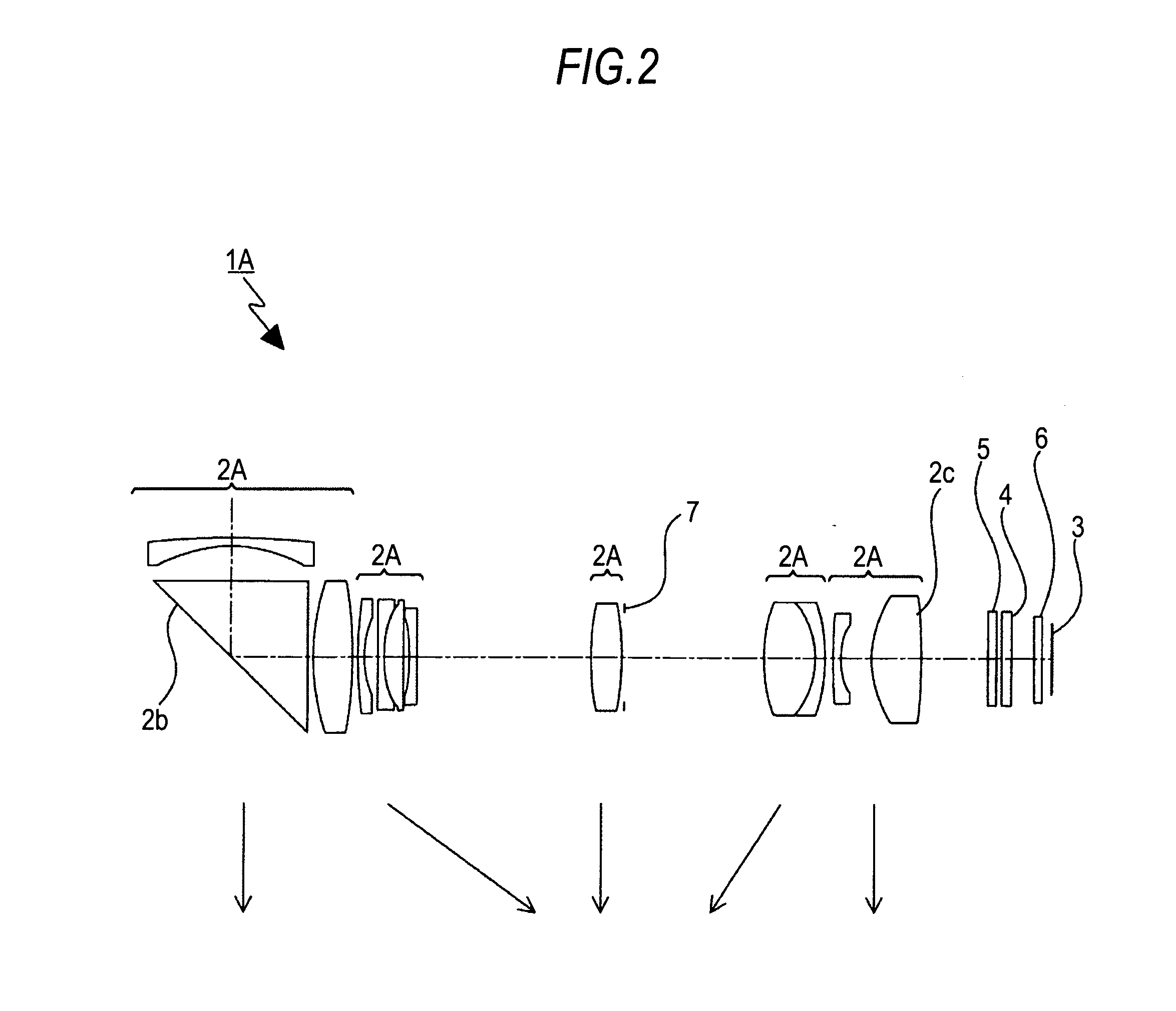
[0024]Accordingly, there is a need for an imaging optical system and an imaging apparatus that can ensure a desirable white balance under temperature conditions of −20° C. to 80° C. regardless of the density of the light control element, and that can realize desirable color reproducibility concerning the red region.
[0069]In this way, a desirable white balance can be ensured, and desirable color reproducibility can be realized concerning the red region.

Problems solved by technology

However, such desirable white balance adjustment under temperature conditions of −20° C. to 80° C. is difficult with the imaging apparatuses equipped with the electrical iris system described in JP-A-7-20529 and JP-A-11-326894.

Method used


Image

  • Imaging optical system and imaging apparatus
  • Imaging optical system and imaging apparatus
  • Imaging optical system and imaging apparatus

Examples


examples

[0133]Specific examples of the light control element 4 and the optical filter 5 are described below with reference to FIG. 4 to. FIG. 9.

[0134]FIG. 4 and FIG. 5 are graphical representations according to First Example, in which FIG. 4 represents the spectral transmission characteristic of the optical filter 5, and FIG. 5 represents the spectral transmission characteristic of the optical filter 5 used in combination with the light control element 4 under varying densities of the light control element 4.

[0135]In FIGS. 5, D1, D2, and D3 represent light control elements of different densities, D1 being of the lowest density, and D3 being of the highest density.

[0136]In First Example, TIRCF(580) / TIRCF(540)=0.798, TIRCF(640) / TIRCF(540)=0.265, and |TIRCF(700) / TIRCF(540)|=0.010, satisfying the conditions (1), (2), and (3).

[0137]As represented in FIG. 4 and FIG. 5, the spectral transmittance gradually decreases toward the longer wavelength side in the red region (wavelengths of 600 nm to 700 ...


PUM


Abstract

An imaging optical system includes: a light control element formed of a dye pigment-containing dichroic guest-host liquid crystal, and that is disposed on a light path to adjust a quantity of incident light for an image sensing device; and an optical filter disposed on the light path, and that includes an infrared absorbing material, the optical filter having a spectral transmittance that satisfies the following conditions (1), (2), and (3)0.6<TIRCF(580) / TIRCF(540)<1.05   (1)0.1<TIRCF(640) / TIRCF(540)<0.5   (2)|TIRCF(700) / TIRCF(540)|<0.05   (3)whereTIRCF(540), TIRCF(580)TIRCF(640) and TIRCF(700) are the spectral transmittance of the optical filter for the light with a wavelength of 540 nm, 580 nm, 640 nm and 700 nm, respectively.

Description

BACKGROUND OF THE INVENTION[0001]1. Field of the Invention[0002]The present invention relates to the technical field of imaging optical systems and imaging apparatuses, specifically to the technical field in which a light control element that adjusts the quantity of incident light for an image sensing device, and an optical filter that includes an infrared absorbing material are used to ensure a desirable white balance regardless of the density of the light control element, and to realize desirable color reproducibility concerning the red region.[0003]2. Description of the Related Art[0004]There have been recent demands for miniaturization of imaging apparatuses, such as digital video cameras and digital still cameras, with maintained high resolution.[0005]To meet such demands, imaging apparatuses have been proposed that include a miniaturized imaging optical system, and a high-density CCD (Charge Coupled Device) or a high-density CMOS (Complementary Metal-Oxide Semiconductor) insta...

Claims


Application Information

Patent Timeline
IPC IPC(8): G03B7/00G02B5/22G02B5/26G02B15/20G02F1/13G02F1/1335H04N5/238
CPCG02B5/04G02B5/223G02B5/226G02B13/001G02F1/13725G02B13/006G02B13/0065G02B13/009G02B15/173G02B13/0045
Inventor YAMANO, HIROKI
Owner SONY CORP
Learn More