
Programmable Communicating Thermostat And System

a thermostat and communication technology, applied in the field of programmable thermostats, can solve the problems of reducing the service life of the air conditioner, and increasing the electrical load

Inactive Publication Date: 2011-01-13
KMC CONTROLS
View PDF23 Cites 85 Cited by
  • Summary
  • Abstract
  • Description
  • Claims
  • Application Information

AI Technical Summary

Benefits of technology

"The present invention is about a programmable thermostat that can communicate with a utility and a system that uses the thermostat. The thermostat receives information from the utility through low voltage power lines and sends the information back to the utility. The thermostat also has a way to avoid heat from affecting its own circuits. The communication is two-way, and can include information about the thermostat's response to a power shed command and its sensed temperature. The technical effect of this invention is to provide a more efficient and effective way to manage energy usage and control the temperature of buildings and homes."

Problems solved by technology

Air conditioners represent significant consumption of electricity.
The utility's systems—indeed the entire national electronic grid—must handle significant differences in electrical loads, which adds tremendous cost.
As we move toward alternative energy sources, these differences in electrical loads can be magnified, such as when the hot (increased air conditioning) weather is also still and dry (resulting in decreased supply of wind and hydroelectric power).
Regardless of the mechanism used, the effective implementation of such a strategy presents many thorny problems.
However, the vast majority of PLC devices involve communication between a transmitter and a receiver both located within a building and made by the same company, rather than between a transmitter or receiver located a significant distance away from the building communicating with another manufacturer's device.
The utility company will thus have many decisions and implementation issues to effectively generate and transmit instructions to each building where the utility seeks to influence the level of energy consumption.
However, wireless communication presents its own set of difficulties, not the least of which is a limited distance of transmission under current FCC standards.

Method used


Image

  • Programmable Communicating Thermostat And System
  • Programmable Communicating Thermostat And System
  • Programmable Communicating Thermostat And System

Examples


Embodiment Construction

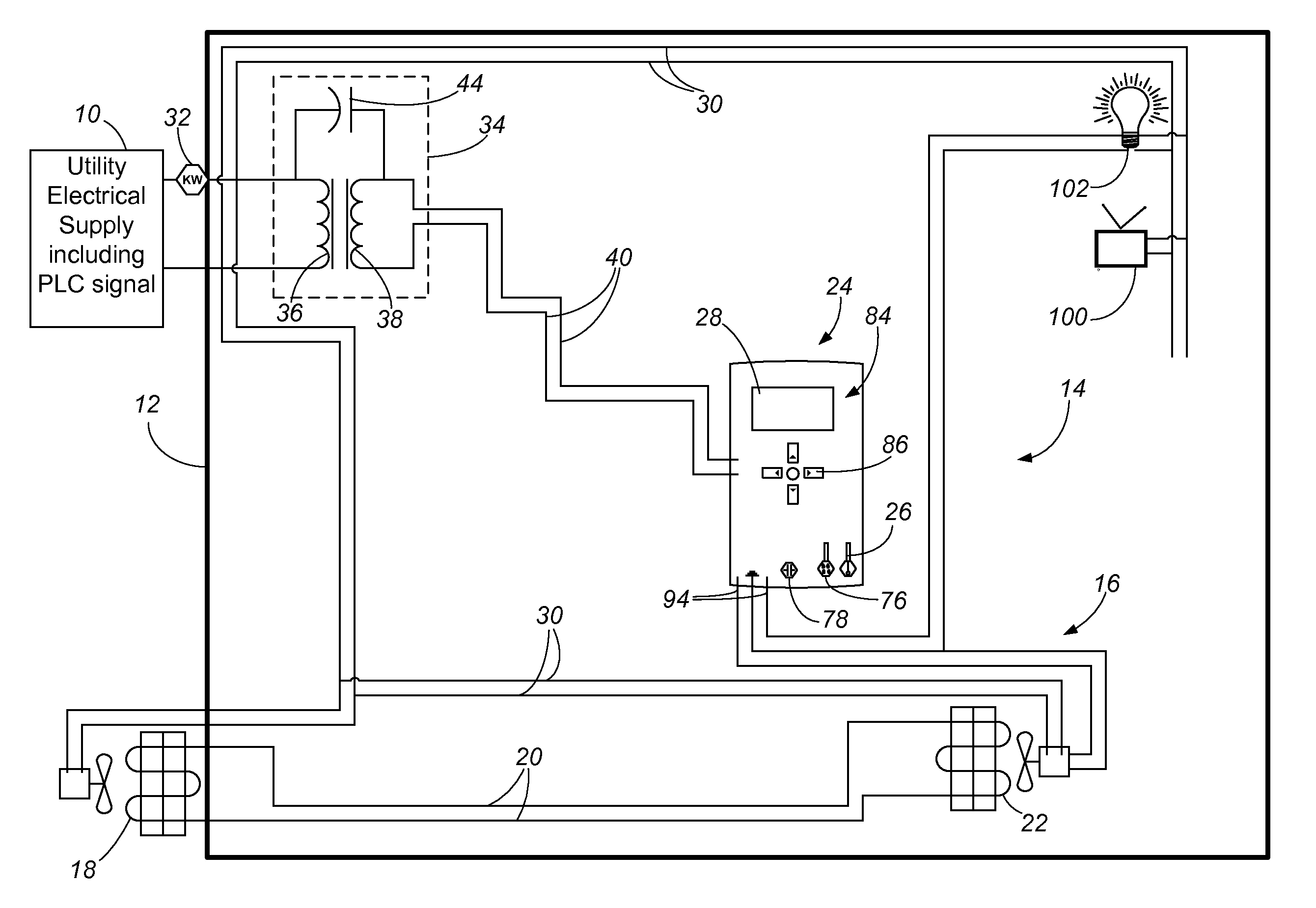
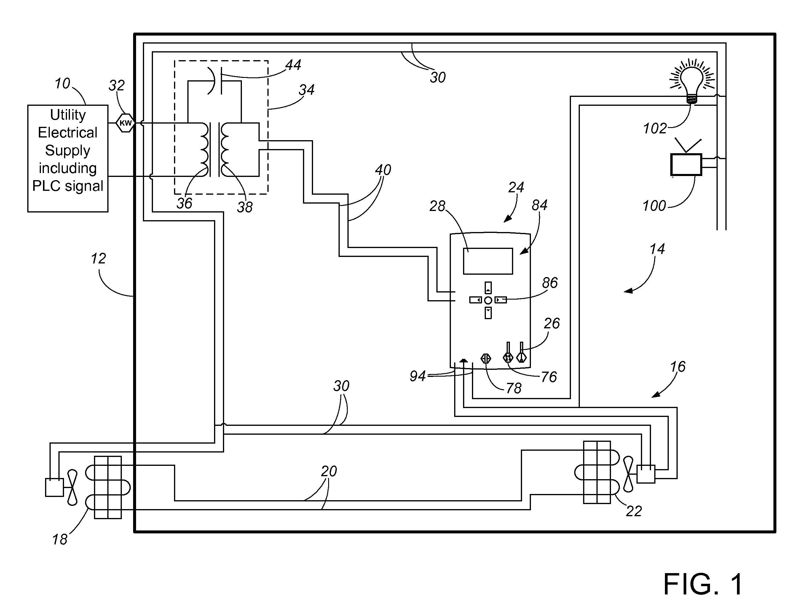
[0014]As shown in FIG. 1, the present invention involves a system in which a utility company 10 is providing energy, typically electricity, to a building 12. The building 12 uses the energy provided for various purposes, including running the heating, ventilation and air conditioning (“HVAC”) system 14 for the building 12. The HVAC system 14 includes known components of common HVAC systems, depicted in this case as a “central” air system 16 with an exterior air conditioner compressor / condenser unit 18 with refrigerant lines 20 running to an interior air conditioner evaporator / fan 22.

[0015]The air conditioner 16 is controlled by a thermostat unit 24 which includes a temperature sensor 26 to measure the temperature of air within the building 12. As typical of advanced thermostats, the thermostat 24 includes a display 28 and controls 86 to enable a building occupant to, among other functions, change the set point temperature for operation of the air conditioner 16. The thermostat 24 is...


PUM


Abstract

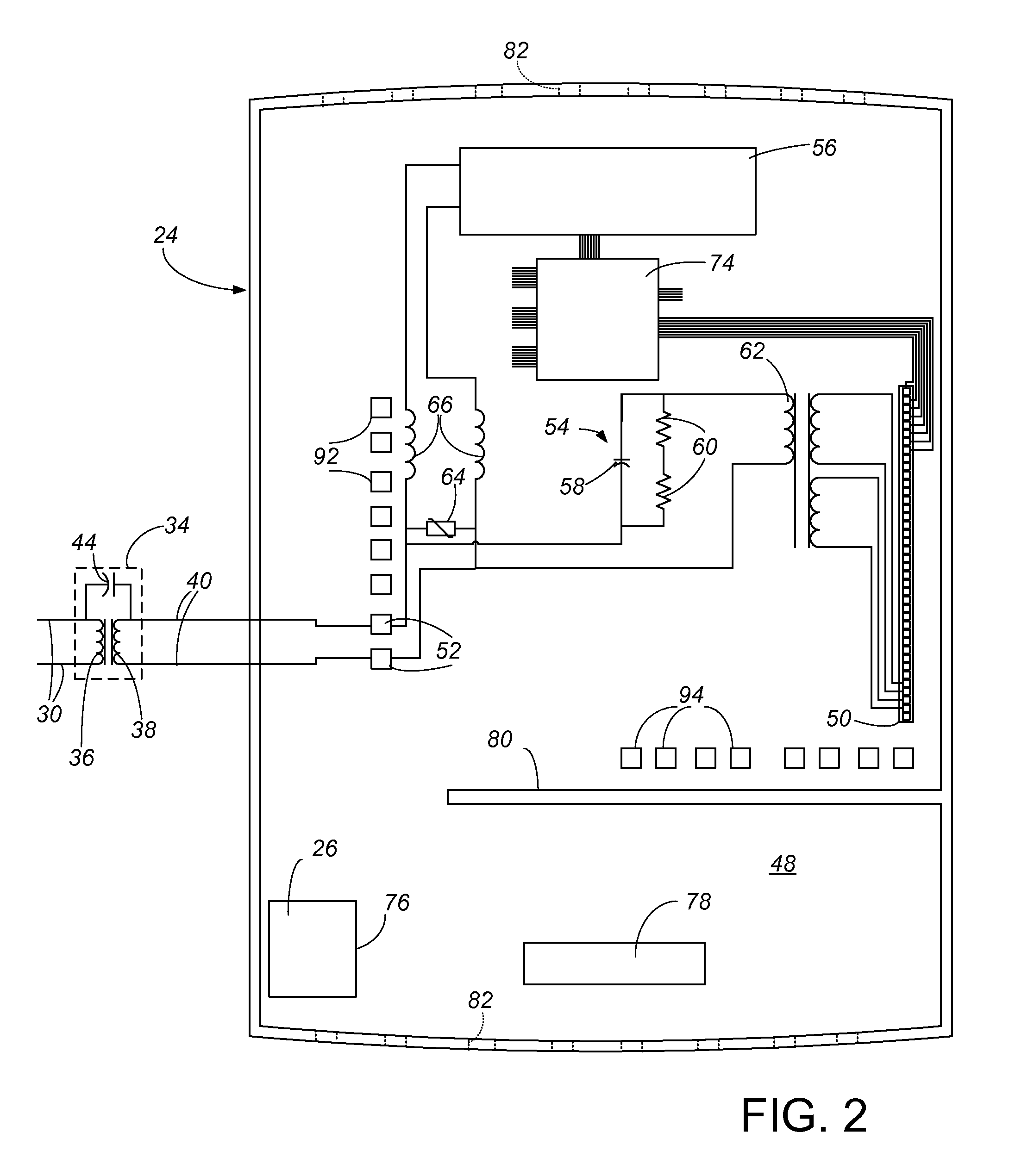
A programmable thermostat has two way communication with a utility using a power carrier line signal across distributed low voltage power lines in a building downstream of an HVAC system transformer. The two way PLC communication includes transmission to the utility of response information regarding the response taken by the thermostat to a power “shed” command, and preferably also includes sensed temperature and / or temperature set point information. The HVAC system transformer includes an integral capacitive bypass path for PLC data transmission across the windings of the transformer. The thermostat positions its temperature sensor to avoid heat given off by the PLC receiver / transmitter and its electrical circuits as well as the thermostat microprocessor and the electrical power circuits therefore.

Description

CROSS-REFERENCE TO RELATED APPLICATION(S)[0001]This application claims priority from Provisional Application No. 61 / 225,040, filed Jul. 13, 2009, entitled PROGRAMMABLE COMMUNICATING THERMOSTAT AND SYSTEM.BACKGROUND OF THE INVENTION[0002]The present invention relates to programmable thermostats, and, more particularly, to programmable thermostats and thermostat systems used in heating, ventilation and air conditioning (“HVAC”) systems for buildings which can communicate with a utility such as through using a power line communication (also known as power line carrier, hereinafter referred to as “PLC”) signal.[0003]Increases in efficiency in utilizing energy are continuously needed, and are becoming even more important with our country's movement off of foreign-provided fossil fuels and into alternative and cleaner energy sources. One of the primary ways in which we use energy is in heating, cooling and ventilating our indoor spaces. Sometimes fossil fuels, such as natural gas, are del...

Claims


Application Information

Patent Timeline
Patent Type & Authority Applications(United States)
IPC IPC(8): G05B11/01
CPCG05B2219/2642G05B15/02
Inventor SHAULL, RANDALL L.WESTPHAL, BRUCE D.HERDEMAN, JAMES ROBERTKEHLER, WAYNE
Owner KMC CONTROLS
Learn More