Bioreactor

a technology of bioreactors and shaft housings, which is applied in the field of bioreactors, can solve the problems of occupying a large volume, complex structure of shaft housings, and inconvenient maintenance of shaft housings, and achieves the effect of simple, cost-effective and compact design and substantial preservation of the compact nature of shaft housings

Active Publication Date: 2011-01-06
SARTORIUS STEDIM BIOTECH GMBH
View PDF11 Cites 23 Cited by
  • Summary
  • Abstract
  • Description
  • Claims
  • Application Information

AI Technical Summary

Benefits of technology

[0012]It has surprisingly been found that when using a radial shaft seal with two lips, as are known for the sealing of annular gaps in relation to rotating shafts between a pressurized hydraulic side and an atmospheric side in wet running or with lubrication of the sealing lip, in the present case permit a sufficient gas seal and liquid seal even when the sealing lips run without lubricant. With unlubricated running, it is possible to dispense with lubricants that contaminate the reactor contents or react with the reactor contents. By using the at least one radial shaft seal, it is possible to dispense with a special disk-shaped sealing collar on the shaft. The shaft housing with the shaft can thus have a simple, cost-effective and compact design.
[0014]According to another preferred embodiment of the invention, a second seal is arranged adjacent to the first seal in the longitudinal direction of the shaft. By virtue of the fact that the two seals are not arranged coaxially with respect to each other in the radial direction but are instead arranged one behind the other in the axial direction, the compact nature of the shaft housing is substantially maintained. The sealing action of the two radial shaft seals arranged one behind the other is thereby increased.

Problems solved by technology

A disadvantage of the above is that the structure of the shaft housing, in conjunction with the seals, is quite complicated and cost-intensive and also takes up quite a large volume.
A disadvantage of this is that these seals are designed as seals running in hydraulic liquid, or at least as lubricated seals, in which the space between the sealing lips is used as a lubricant depot.

Method used


Image

  • Bioreactor
  • Bioreactor
  • Bioreactor

Examples


Embodiment Construction

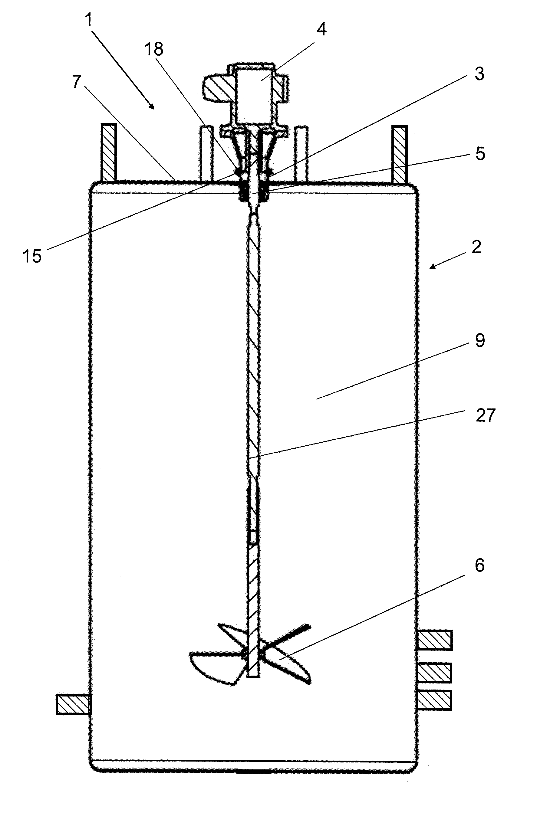
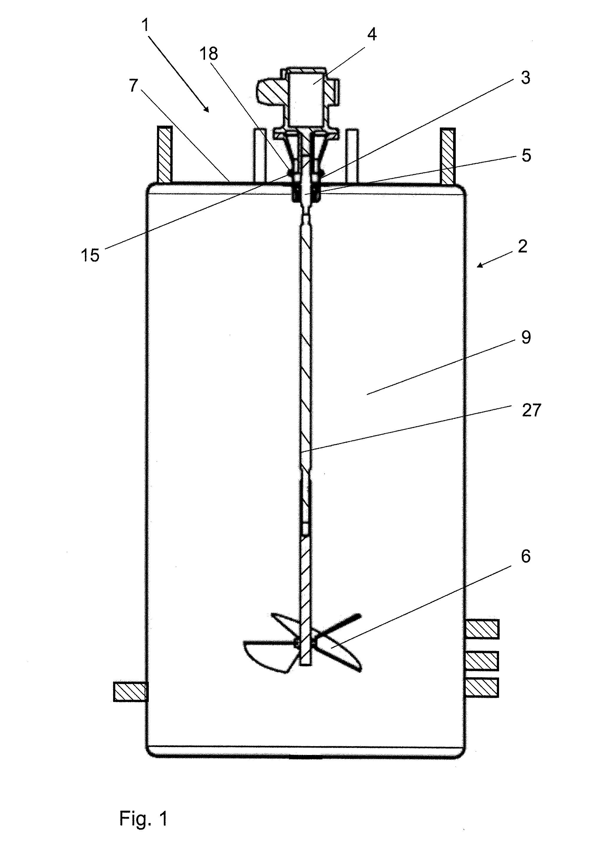
[0023]A bioreactor 1 basically comprises a container 2, a shaft housing 3, a drive 4, a shaft 5 and a stirrer 6.

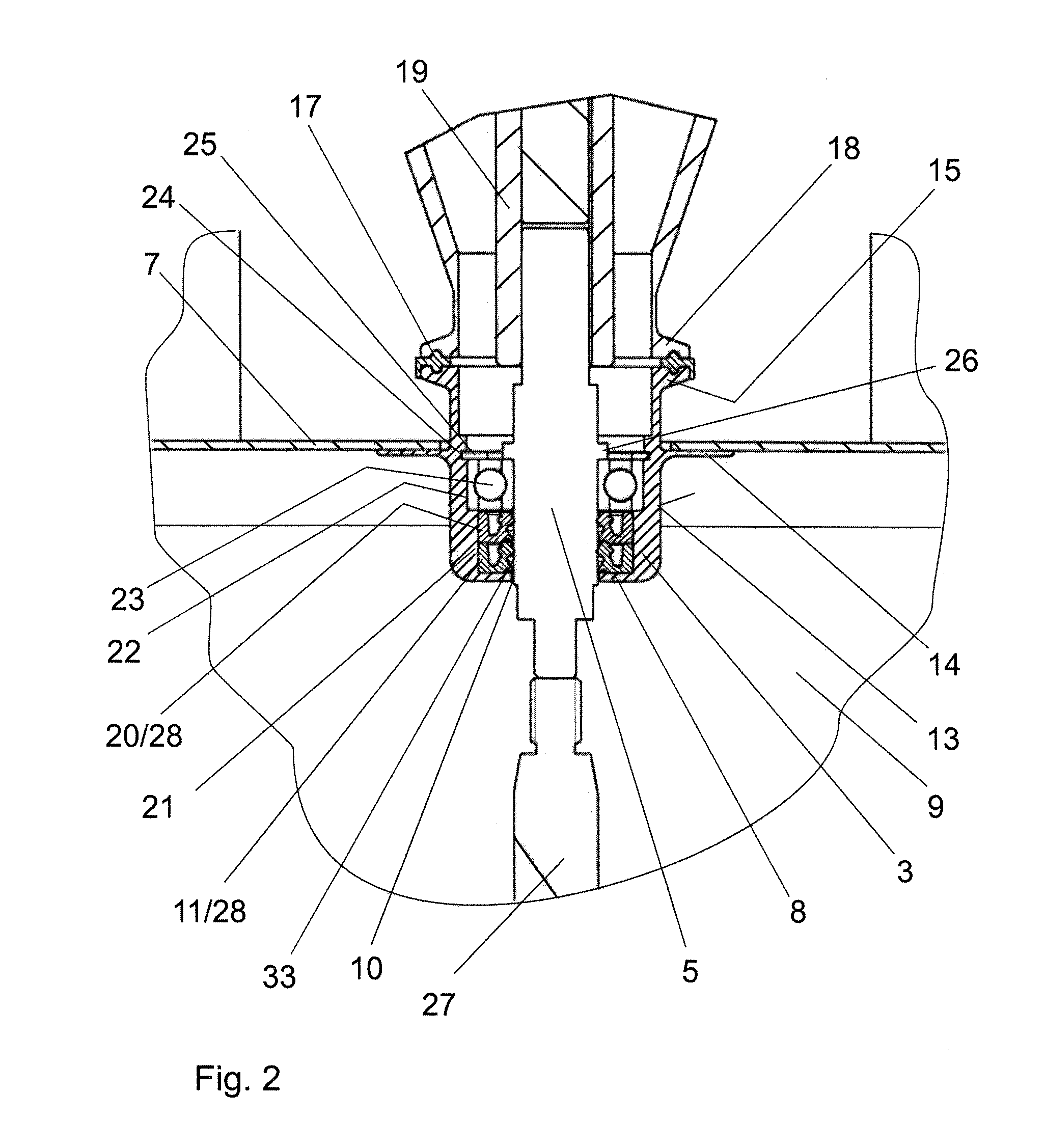
[0024]The container 2 has a flexible wall 7 which at the top in the vertical direction is securely connected to the shaft housing 3 for passage of the shaft 5. The shaft housing 3 is pot-shaped and its lower part, comprising a floor 8, protrudes into an interior 9 of the container 2. The floor 8 has a through-opening 10 for the shaft 5 and forms a support bearing for a first seal 11, which bears with its end face 12 on the floor 8. The shaft housing 3 has a cylindrical outer wall 13 with a radially extending, flat collar 14 which is connected to the adjacent flexible wall 7 of the container 2. The connection can be made, for example, by adhesive bonding or ultrasonic welding.

[0025]At its upper edge directed away from the floor 8, the shaft housing 3 has a flange 15 with an annular groove 16 for receiving a flange seal 17. The drive 4 can be flanged onto the flange 15 with ...


PUM


Abstract

A bioreactor (1) having a container (2), a shaft housing (3) for guiding a shaft (5) through a wall (7), a stirrer (6) connected to the shaft (5) in the interior (9) of the container (2), and a drive (4) arranged outside the container (2) and connectable to the shaft (5). The shaft (5) is mounted in the shaft housing (3) via at least one ball bearing (23) and is sealed in relation to the shaft housing (3) by at least one seal (11, 20). The seal (11, 20) is configured as a radial shaft seal (28) having two sealing lips (30, 31) that are arranged one behind the other in the longitudinal direction of the shaft (5) and are able to run on the shaft (5) without lubricant.

Description

BACKGROUND OF THE INVENTION[0001]1. Field of the Invention[0002]The invention relates to a bioreactor having a container, a shaft housing for guiding a shaft through a wall, a stirrer connected to the shaft in the interior of the container, and a drive arranged outside the container and connectable to the shaft, said shaft being mounted in the shaft housing via at least one ball bearing and being sealed in relation to the shaft housing by at least one seal.[0003]2. Description of the Related Art[0004]Bioreactors having a container with a flexible wall are being increasingly used, particularly as disposable bioreactors, in pharmacy and biotechnology.[0005]US 2006 / 0280028 A1 discloses a bioreactor having a container with a flexible wall, through which wall a shaft is guided in order to drive a stirrer arranged in the interior of the container. A shaft housing is connected to the flexible wall via a sealing flange. The shaft is mounted in the shaft housing via two ball bearings. The sh...

Claims


Application Information

Patent Timeline
IPC IPC(8): C12M1/02
CPCB01F7/1695B01F15/00831B01F15/0085F16C33/76C12M27/02C12M37/04C12M23/26B01F27/88B01F35/51B01F35/513
Inventor VAN DEN BOOGAARD, JUERGENGRELLER, GERHARDLUDWIG, JENSREIF, OSCAR-WERNER
Owner SARTORIUS STEDIM BIOTECH GMBH
Why Eureka
Try Eureka