
Video coder

a video coder and video technology, applied in the field of video coding, can solve the problems of initial playback delay over the possible playback delay for the subset of temporal scalable bitstream, and achieve the effect of efficient memory buffer consumption

Active Publication Date: 2011-01-06
NOKIA TECHNOLOGLES OY
View PDF6 Cites 92 Cited by
  • Summary
  • Abstract
  • Description
  • Claims
  • Application Information

AI Technical Summary

Benefits of technology

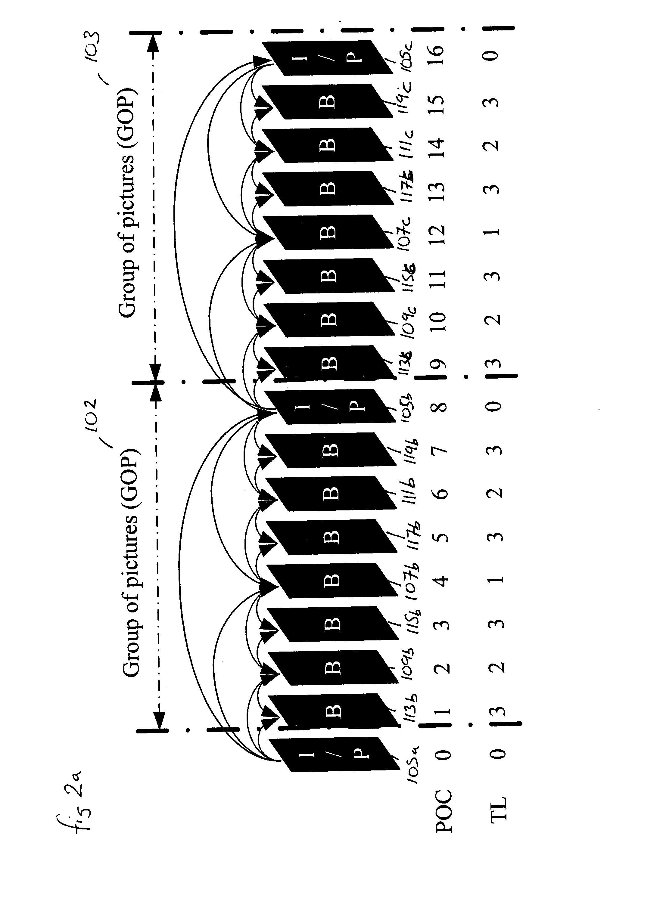
[0128]The advantages of implementing the embodiments of the invention can be explained by the following example. A streaming server may contain a temporal scalable bitstream, for which the required decoded picture buffer (DPB) size is equal to N1 frames. The temporal scalable bitstream contains a lower temporal layer for which the required DPB size is equal to N2 frames, where N2<N1. The profile and level of the entire bitstream are the same as the lower temporal layer bitstream. A streaming client is able to decode the lower temporal layer but unable to decode the entire bitstream due to insufficient memory available. After the client requests the video content from the server, the server informs the required DPB size, among others, to the client.

Problems solved by technology

These memory control methods however are problematic when some highest temporal layers are discarded.
There is another similar problem.
In such a system the decoder that decodes a subset of a temporal scalable bitstream would wait for extra pictures to be decoded to start output, which would cause an initial playback delay over the possible playback delay for the subset of the temporal scalable bitstream.

Method used


Image

  • Video coder
  • Video coder
  • Video coder

Examples


first embodiment

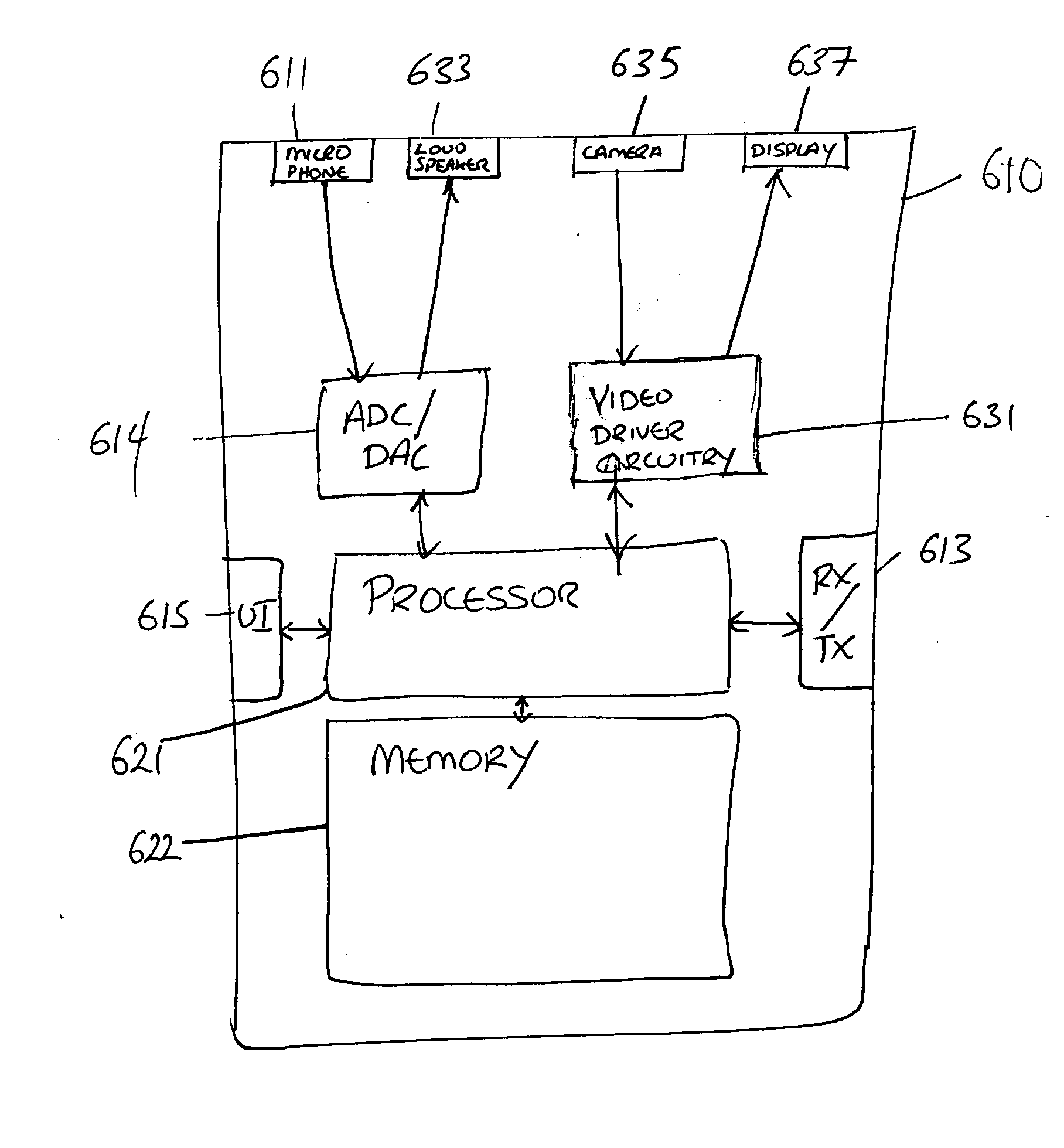
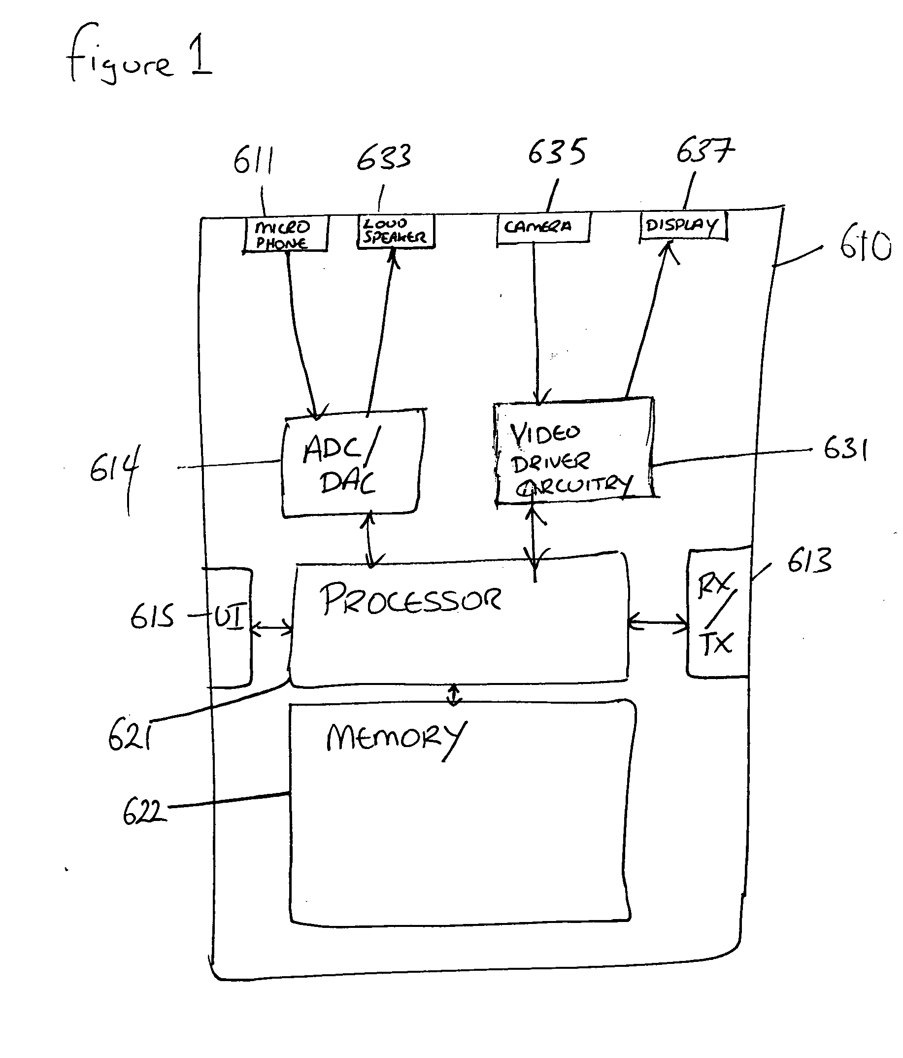
[0111]FIGS. 3a and 3b show the present invention where the above may be implemented to improve the device as shown in FIG. 1. The operation of the embodiments as shown in FIGS. 3a and 3b is further described with respect to FIG. 4.

[0112]FIG. 3a shows a schematic view of a video encoder 301 according to a first embodiment of the present invention. The video encoder 301 receives a raw data stream 307 and outputs an encoded data stream with layer information. The video encoder comprises a scalable data encoder 303 which receives the raw data stream 307 and is connected to a message forming unit 305. The message forming unit furthermore outputs the encoded video data 309.

[0113]The scalable data encoder 303 receives the raw data stream 307 which is shown in FIG. 4 in step 501.

[0114]The scalable data encoder then encodes the data to produce one or more scalable encoded layers. This operation is shown in FIG. 4 in step 503.

[0115]The scalable data encoder further deduces the scalability inf...

second embodiment

[0131]In the invention, the same indication information as above may be included in the scalability information SEI message as specified in the draft SVC standard and not in a separate SEI message such as defined above. The indication information is thus passed to the receiver along with other scalability information for each temporal level as signalled in the scalability information SEI message. In such embodiments of the invention the message deforming unit is configured to extract the indication information from fields within the scalability information SEI message.

[0132]In a further embodiment of the invention SEI messages are not used to transfer the scalable indication information. In these further embodiments of the invention the scalable indication information is included in a container file where the temporal scalable bitstream is stored. In such embodiments the fields max_dec_frame_buffering and num_reorder_frames are included in the TierinfoBox as defined in the latest dr...


PUM


Abstract

An encoder for encoding a video signal, wherein the encoder is configured to generate an encoded scalable data stream comprising a base layer and at least one enhancement layer, wherein the encoder is further configured to generate information associated with each of the base layer and the at least one enhancement layer.

Description

FIELD OF THE INVENTION[0001]The present invention relates to video coding, and in particular, but not exclusively to scalable video coding.BACKGROUND OF THE INVENTION[0002]Video signals are coded for example to enable an efficient transmission or storage of the video signals. These codes are grouped into defined standards defining how to encode and decode such video signals.[0003]Video coding standards include ITU-T H.261, ISO / IEC MPEG-1 Visual, ITU-T H.262 or ISO / IEC MPEG-2 Visual, ITU-T H.263, ISO / IEC MPEG-4 Visual and ITU-T H.264 (also known as ISO / IEC MPEG-4 Advanced Video Coding (AVC) standard). There are currently efforts underway with regards to the development of further video coding standards. One such further standard under development is the scalable video coding (SVC) standard. Another further standard under development is the multi-view video coding (MVC). Both the SVC and MVC standards are intended to add features to the H.264 / AVC standard described above.[0004]The lat...

Claims


Application Information

Patent Timeline
Patent Type & Authority Applications(United States)
IPC IPC(8): H04N7/26H04N19/30H04N19/152
CPCH04N19/70H04N19/423H04N19/30H04N19/152
Inventor WANG, YE-KUIHANNUKESELA, MISKA MATIAS
Owner NOKIA TECHNOLOGLES OY
Learn More