Quick release bench vise system

Inactive Publication Date: 2011-01-06
SEBER DESIGN GROUP
View PDF9 Cites 2 Cited by
  • Summary
  • Abstract
  • Description
  • Claims
  • Application Information

AI Technical Summary

Benefits of technology

[0006]The second channel includes a threaded surface for engaging the threaded shaft, and the first channel includes a smooth surface to allow the threaded shaft to easily slide past. The boss cover is pivotable relative to the boss between a first and second position. In the first position the threads of the shaft engage the threads within the shaft-receiving bore. In the second position the threads of the shaft are disengaged from the threads within the shaft-receiving bore so that the second jaw can slide relative to the first jaw without rotation of the threaded shaft.

Problems solved by technology

Rotation of the handle results in incremental, linear movement of one of the jaws toward or away from the other jaw.
It can be time consuming and tedious to achieve a great amount of movement of the jaws relative to one another.

Method used


Image

  • Quick release bench vise system
  • Quick release bench vise system
  • Quick release bench vise system

Examples


Embodiment Construction

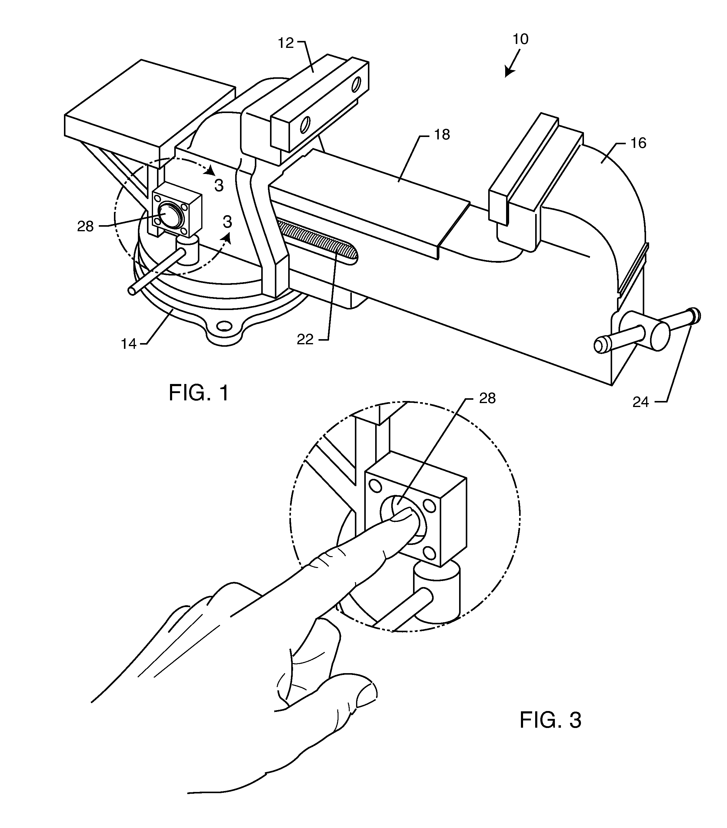
[0021]FIG. 1 illustrates a perspective view of an exemplary quick release bench vise 10 which embodies the present invention. The vise 10 includes a first jaw 12 which can be fastened to a work bench or table through its flat base 14 using screws, bolts, C-clamps, or any other suitable fastening technique. As with most bench vises, the first jaw 12 can also be rotated and locked into place using conventional methods. A second jaw 16 is moveable relative to the first jaw 12. In this embodiment, the second jaw 16 has an elongated arm 18 which translates within a passageway 20 through the first jaw 12, allowing the jaws to come together to hold a work piece therebetween.

[0022]Rotatably fixed to the second jaw 16 is a threaded shaft 22. The threaded shaft 22 is parallel to the elongated arm 18 and also resides within the passageway 20 of the first jaw 12. The threaded shaft 22 may be rotated with a traditional handle 24 attached to the threaded shaft 22 on an end extending from second j...


PUM


Abstract

A quick release vise includes a first and second jaw moveable relative to the first jaw, and a threaded shaft rotatably fixed to the second jaw. A shaft receiver is fixed relative to the first jaw and includes a boss and a boss cover that is moveable relative to the boss. The boss and the boss cover have channels which cooperatively define an at least partially threaded shaft-receiving bore. The boss cover is moveable between a first position wherein the threads of the shaft engage threads within the shaft-receiving bore, and a second position wherein the threads of the shaft are disengaged from the threads within the shaft-receiving bore.

Description

BACKGROUND OF THE INVENTION[0001]The present invention is generally directed to vises for holding work pieces. More particularly, the present invention is directed to a quick release mechanism for a vise which allows fast and easy movement of a vise clamping jaw.[0002]Vises have been known in the art as a common mechanism for holding a work piece in a stationary position while the work piece is being worked on, treated or repaired. Typically, a work piece to be held in the vise is placed between a pair of jaws, wherein one of the jaws is stationary and the other jaw is movable relative to the stationary jaw so as to tighten the jaws around the work piece.[0003]An operator controls movement of the jaws by rotating a handle that is attached to a threaded shaft mechanically coupling the two jaws. Rotation of the handle results in incremental, linear movement of one of the jaws toward or away from the other jaw. It can be time consuming and tedious to achieve a great amount of movement ...

Claims


Application Information

Patent Timeline
IPC IPC(8): B25B1/12
CPCB25B1/24B25B1/125
Inventor SEBER, BRETT P.TOM, WESLEY JAMES
Owner SEBER DESIGN GROUP
Why Eureka
Try Eureka