Recording apparatus and pattern forming method

a recording apparatus and pattern technology, applied in the direction of printing, other printing apparatus, etc., can solve the problems of deterioration of the quality of the recorded image, defective discharge of ink from the recording head, and the occurrence of the defective discharge barely being detected

Inactive Publication Date: 2010-12-30
CANON KK
View PDF3 Cites 24 Cited by
  • Summary
  • Abstract
  • Description
  • Claims
  • Application Information

AI Technical Summary

Benefits of technology

[0008]The present invention is directed to provide a recording apparatus that can detect occurrence of defective discharge by detecting whether a recording omission occurs at a center of a pattern.
[0011]According to the present invention, a user can detect occurrence of defective discharge by detecting whether a recording omission occurs at a center of a pattern. Thus, detection of defective discharge becomes easy.

Problems solved by technology

In an ink jet recording apparatus, one of causes for quality deterioration of a recorded image is defective discharge of ink from the recording head.
However, both the visual method and the method using the optical sensor have a common problem in that the occurrence of the defective discharge barely is detected when the defective discharge occurs at an end of a nozzle array of the recording head.
However, when the recording omission occurs at an end of the nozzle array, the recording omission does not appear as a slit-like recording omission generated at the center of the nozzle array, so that the user tends to misunderstand that the discharging state is normal.
In such a case, the similar problem occurs.
However, when the defective discharge occurs at the ends of the nozzle array, the ends of the test image are missed.
Therefore, in both cases of the visual method or the method using the optical sensor, there is a problem that a user hardly detects the defective discharge compared with the case where the slit-like recording omission is generated at the center of the test image.
Particularly, when the optical sensor with a small number of effective elements is used, the defective discharge at the ends of the nozzle array is not detected correctly.
However, the optical sensor having a small number of effective elements cannot acquire the position information of the test image.
Therefore, even when the defective discharge occurs at the ends of the nozzle array, a user recognizes that an end of a discharging part is an end of the test image, and cannot detect the defective discharge at the end of the nozzle array.

Method used


Image

  • Recording apparatus and pattern forming method
  • Recording apparatus and pattern forming method
  • Recording apparatus and pattern forming method

Examples


Embodiment Construction

[0027]Various exemplary embodiments, features, and aspects of the invention will be described in detail below with reference to the drawings.

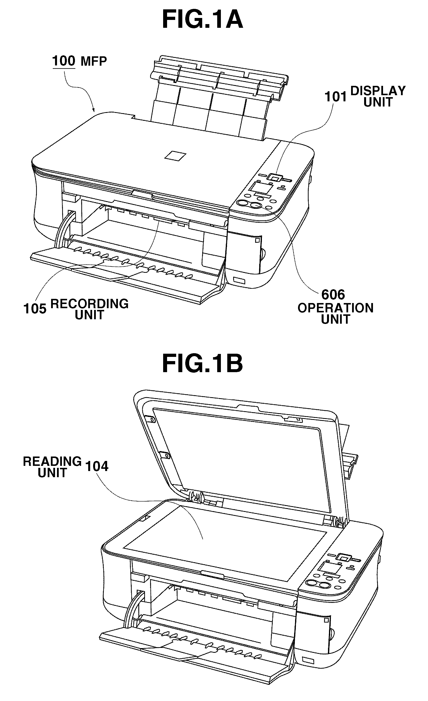
[0028]FIG. 1 is an apparatus perspective view schematically illustrating a multi function printer (MFP) 100 as an example of an inkjet recording apparatus to which the present invention can be applied. As illustrated in FIGS. 1A and 1B, the MFP 100 includes a display unit 101, a reading unit 104, a recording unit 105, and an operation unit 606.

[0029]As illustrated in FIG. 1A, the MFP 100 is installed in a state where the reading unit 104 is closed. When a recording medium is scanned, the user opens a reading cover of the reading unit 104, and puts a document on a glass plate, as illustrated in FIG. 1B. Then, the user closes the reading cover and causes the MFP 100 to execute desired functions, such as a copy function and a scanner function, by pressing a start key provided at the operation unit 606.

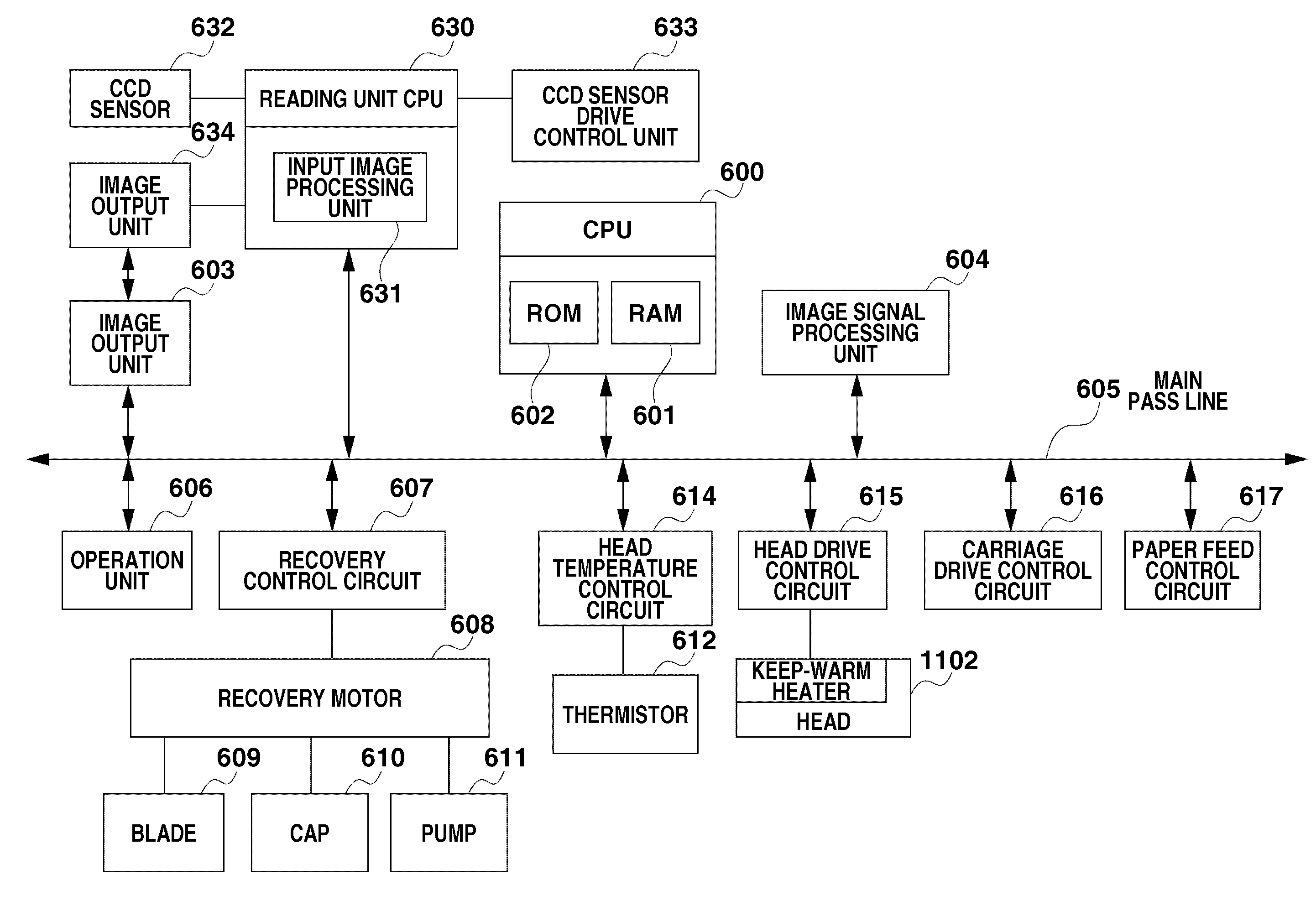
[0030]FIG. 2 illustrates a configuration of th...


PUM


Abstract

A pattern forming method that includes forming a pattern for detecting defective discharges of a plurality of ink discharging nozzles and recording a first dot pattern with the plurality of ink discharging nozzles. The pattern forming method also includes recording a second dot pattern to be adjacent to at least one side of the first dot pattern in the predetermined direction.

Description

BACKGROUND OF THE INVENTION[0001]1. Field of the Invention[0002]The present invention relates to a recording apparatus that discharges ink from a recording head and performs recording, and a pattern forming method for detecting defective discharge of the recording head.[0003]2. Description of the Related Art[0004]In an ink jet recording apparatus, one of causes for quality deterioration of a recorded image is defective discharge of ink from the recording head. In a conventional method for detecting defective discharge from the recording head, a user records a test image (a defective discharge detection pattern) on a recording medium, and visually checks whether the recorded test image includes recording omissions due to the defective discharge. Recently, the recording apparatus has detected defective discharge by reading the recorded recording medium using an optical sensor attached to a carriage or a scanner unit instead of visual detection.[0005]However, both the visual method and...

Claims


Application Information

Patent Timeline
IPC IPC(8): B41J29/38
CPCB41J2/2142B41J29/38B41J29/393B41J2/04556B41J2/04558B41J2029/3935B41J2/0451
Inventor YOSHIKAWA, HIROKAZUKANDA, HIDEHIKO
Owner CANON KK
Why Eureka
Try Eureka