Configurable pulse generator

a generator circuit and generator technology, applied in the direction of generating/distributing signals, pulse techniques, instruments, etc., can solve the problems of inability to send off-chip pulses to be measured using specialized measuring equipment, inability to accurately measure the width of such pulses, and inability to use on-chip structures to measure the duration of pulses

Active Publication Date: 2010-12-30
ORACLE INT CORP
View PDF4 Cites 2 Cited by
  • Summary
  • Abstract
  • Description
  • Claims
  • Application Information

AI Technical Summary

Benefits of technology

[0011]In some embodiments, each feedback path can include one or more circuit elements in the pulse circuit and one or more circuit elements coupled to an output of the pulse circuit.
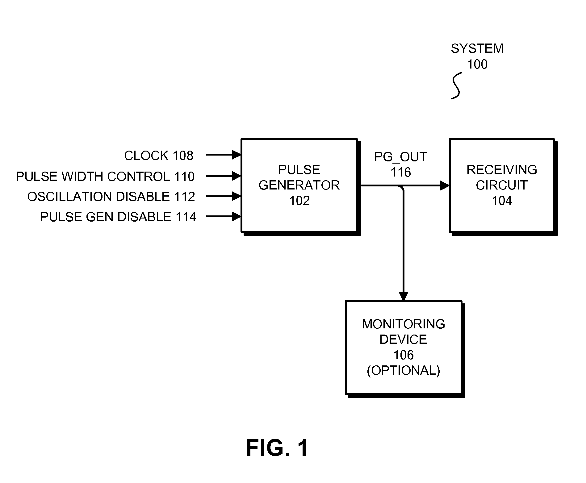
[0012]In some embodiments, the circuit includes a frequency-reduction circuit coupled to the pulse generator. The frequency-reduction circuit is configured to take the oscillating signal output by the pulse generator as an input and to output a signal with a frequency that is a predetermined fraction of the frequency of the oscillating signal output by the pulse generator.
[0013]In some embodiments, the circuit includes a recursive multiplexer coupled to the pulse generator circuit and to one or more other pulse generator circuits. The recursive multiplexer includes a set of OR gates coupled in series. One of the inputs of each OR gate is coupled to a different one of the pulse generator circuits, and another input of each OR gate is coupled to either VSS or to an output of a previous OR gate. The last OR gate in the recursive multiplexer outputs a signal or a combination of signals received by the recursive multiplexer from the pulse generator circuits.

Problems solved by technology

However, accurately measuring the width of such pulses is difficult because of the short duration of the pulses.
More specifically, because the pulses are so short, it is effectively impossible to send the pulses off-chip to be measured using specialized measuring equipment.
In addition, measuring the duration of the pulses using on-chip structures is also impractical because of the complexity and size of such on-chip structures.

Method used


Image

  • Configurable pulse generator
  • Configurable pulse generator
  • Configurable pulse generator

Examples


Embodiment Construction

[0025]The following description is presented to enable any person skilled in the art to make and use the described embodiments, and is provided in the context of a particular application and its requirements. Various modifications to the described embodiments will be readily apparent to those skilled in the art, and the general principles defined herein may be applied to other embodiments and applications without departing from the spirit and scope of the described embodiments. Thus, the described embodiments are not limited to the embodiments shown, but are to be accorded the widest scope consistent with the principles and features disclosed herein.

[0026]The data structures and code described in this detailed description are typically stored on a computer-readable storage medium, which may be any device or medium that can store code and / or data for use by a computer system. The computer-readable storage medium includes, but is not limited to, volatile memory, non-volatile memory, m...


PUM


Abstract

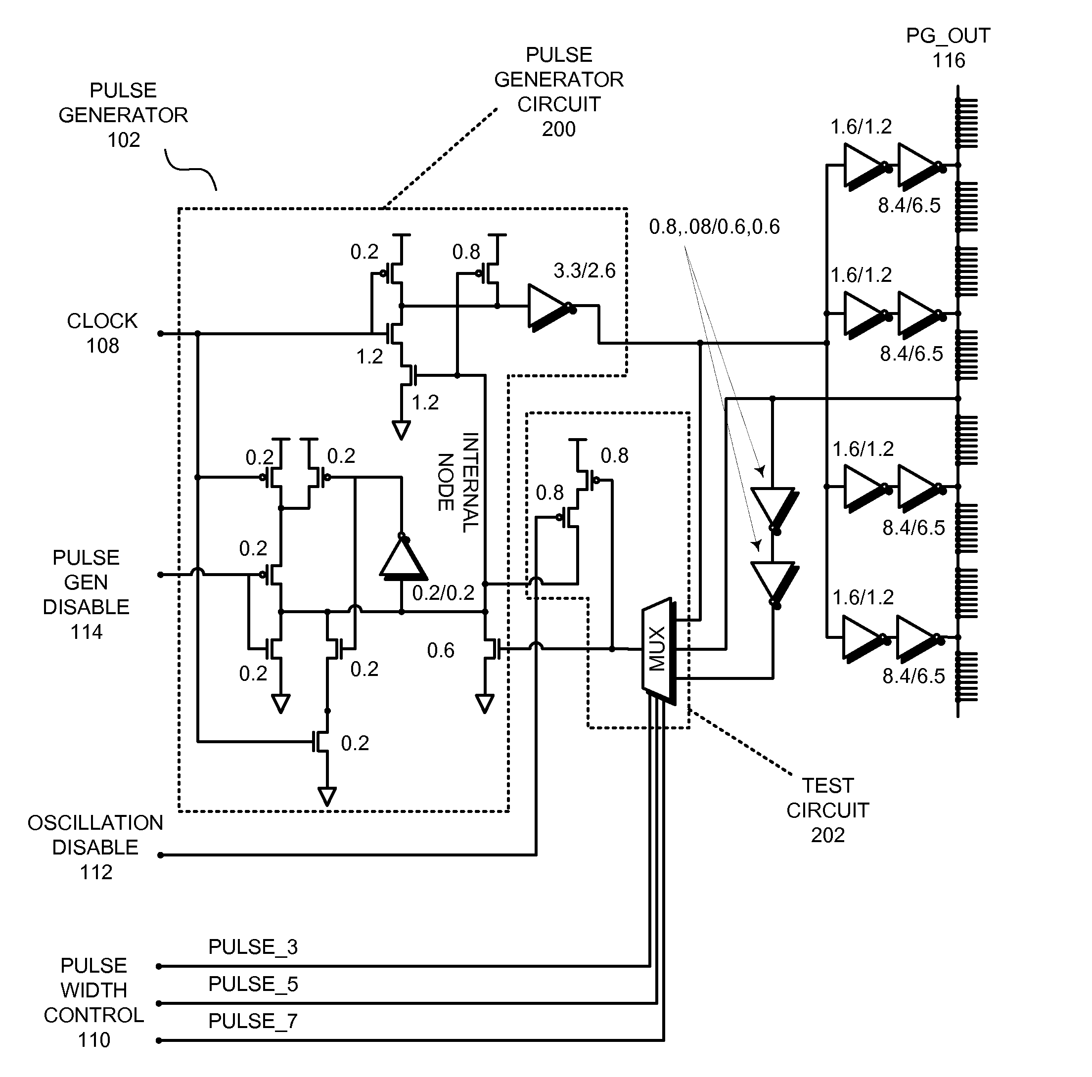
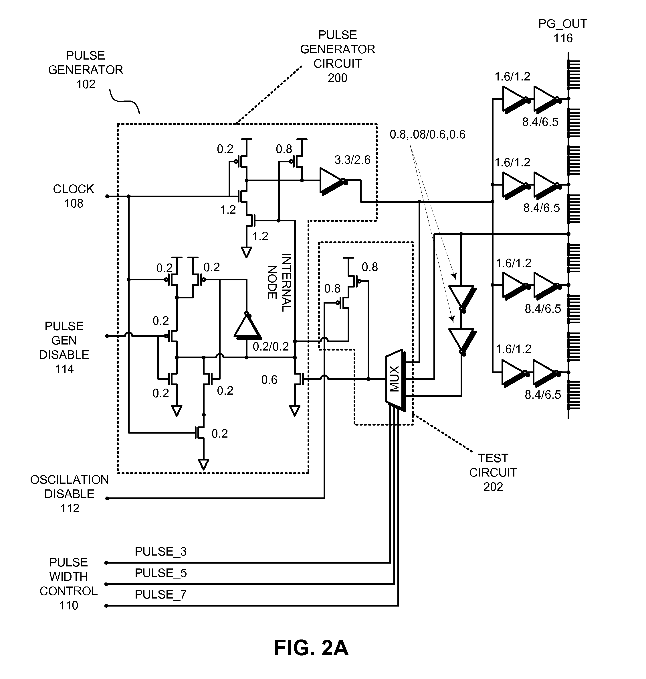
The described embodiments provide a circuit that can be configured as a pulse generator or as an oscillator. The circuit includes a pulse generator circuit and a test circuit that is coupled to the pulse generator circuit. In the described embodiments, an disable signal is coupled to the test circuit. When the disable signal is asserted, the test circuit is disabled, and the pulse generator circuit outputs pulses of a predetermined duration. In contrast, when the disable signal is deasserted, the test circuit is enabled, and the pulse generator circuit outputs an oscillating signal.

Description

RELATED APPLICATIONS [0001]This application is related to U.S. patent application Ser. No. not yet assigned, entitled “Inverting Difference Oscillator”, filing date 30 Jun. 2009, by inventors Robert P. Masleid and Anand Dixit, (atty. docket no. SUN09-0650). This application is further related to U.S. patent application Ser. No. 12 / 425,176, entitled “Economy Precision Pulse Generator,” filing date 16 Apr. 2009, by inventors Robert P. Masleid, David J. Greenhill, and Bijoy Kalloor.BACKGROUND[0002]1. Field of the Invention[0003]The described embodiments relate to pulse generator circuits. More specifically, the described embodiments relate to a configurable pulse generator circuit.[0004]2. Related Art[0005]Many integrated circuits use pulsed signals for control and timing purposes. For example, microprocessors, application-specific integrated circuits (ASICS), or other high-speed integrated circuits can include pulse latches that are controlled or timed using pulsed signals. In another...

Claims


Application Information

Patent Timeline
Patent Type & Authority Applications(United States)
IPC IPC(8): G06F1/04
CPCH03K3/354H03K2005/00293H03K19/173Y10S331/03
Inventor MASLEID, ROBERT P.DIXIT, ANAND
Owner ORACLE INT CORP
Why Eureka
Try Eureka