
Substrate rotating and oscillating apparatus for rapid thermal process

a rotating and oscillating apparatus technology, applied in the field of rapid thermal process substrate rotating and oscillating apparatus, can solve the problems of uniform heat overlapping section b, inevitably generated, and difficult to achieve uniform heating

Active Publication Date: 2010-12-23
AP SYST INC
View PDF1 Cites 3 Cited by
  • Summary
  • Abstract
  • Description
  • Claims
  • Application Information

AI Technical Summary

Benefits of technology

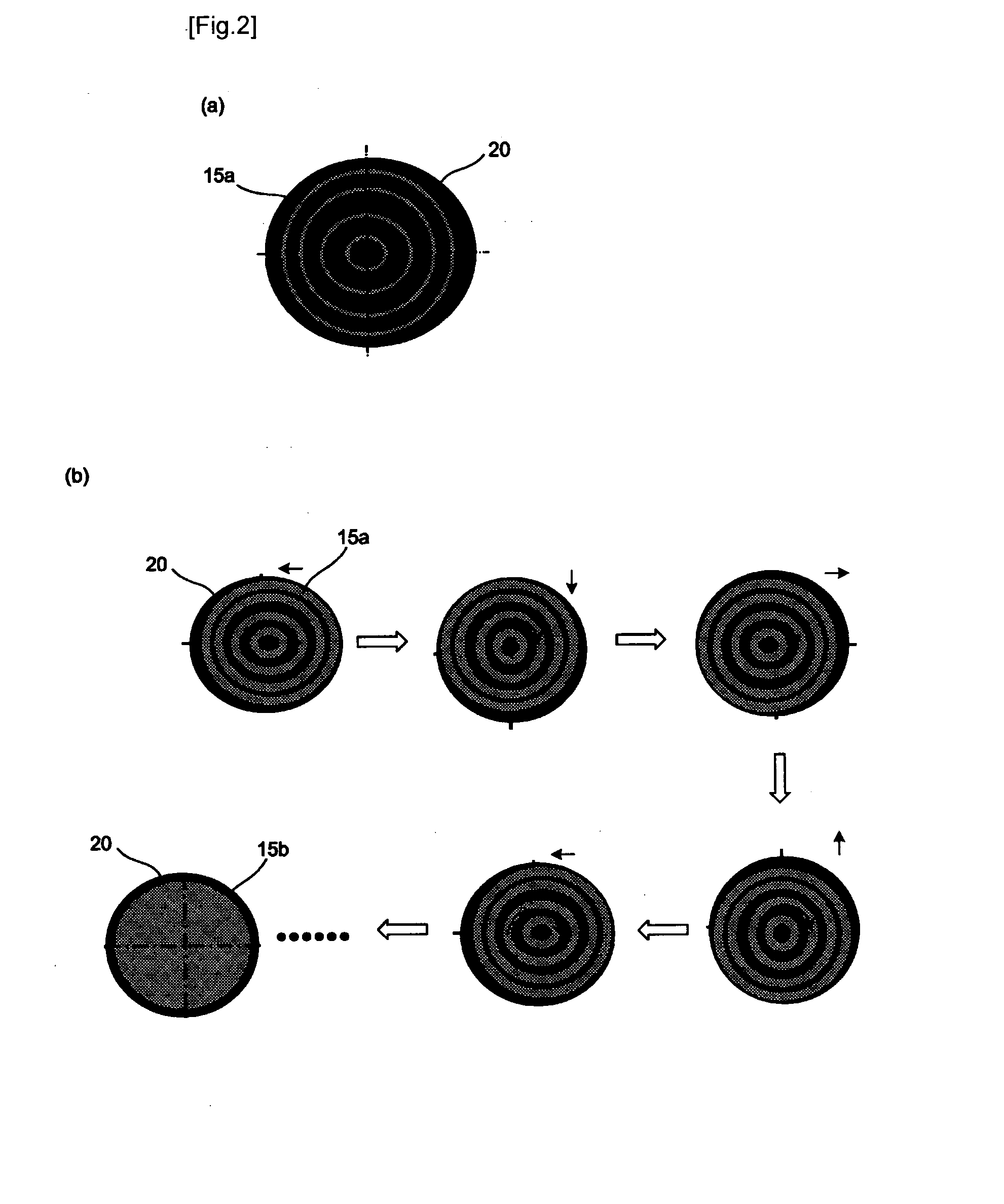
[0005]Therefore, the present invention has been made in view of the above problems, and it is an object of the present invention to provide a substrate rotating and oscillating apparatus for a rapid thermal process (RTP), capable of solving the problem of nonuniform heating of a substrate, by increasing a degree of freedom regarding movement of the substrate and thereby oscillating the substrate horizontally in all directions as well as rotating the substrate horizontally.Technical Solution
[0014]The upper center rotational shaft may be mounted with a centering cam, and the oscillation plate may be formed with a centering hole extended upward from the oscillation hole to insert the centering cam therein. The centering cam has an inverse truncated cone shape which is narrowing downward, and the centering hole also has the inverse truncated cone shape to correspondingly insert the centering cam therein. A bearing may be mounted between the centering cam and the upper center rotational shaft such that the centering cap can be rotated independently from the upper center rotational shaft.

Problems solved by technology

However, as the size of substrates is increasing, it becomes difficult to achieve the uniform heating.
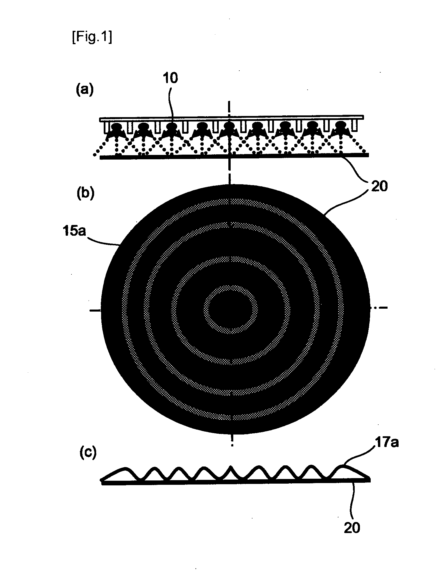
However, in spite of trying various substrate rotating methods, ununiform heat overlapping sections 15a are inevitably generated as shown in FIG. 1.
Thus, mere horizontal rotation of the substrate is insufficient to prevent ununiform heating of the substrate.

Method used


Image

  • Substrate rotating and oscillating apparatus for rapid thermal process
  • Substrate rotating and oscillating apparatus for rapid thermal process
  • Substrate rotating and oscillating apparatus for rapid thermal process

Examples


embodiment 1

Horizontal Rotation with Horizontal Oscillation in Multipole-Magnetized Magnet System

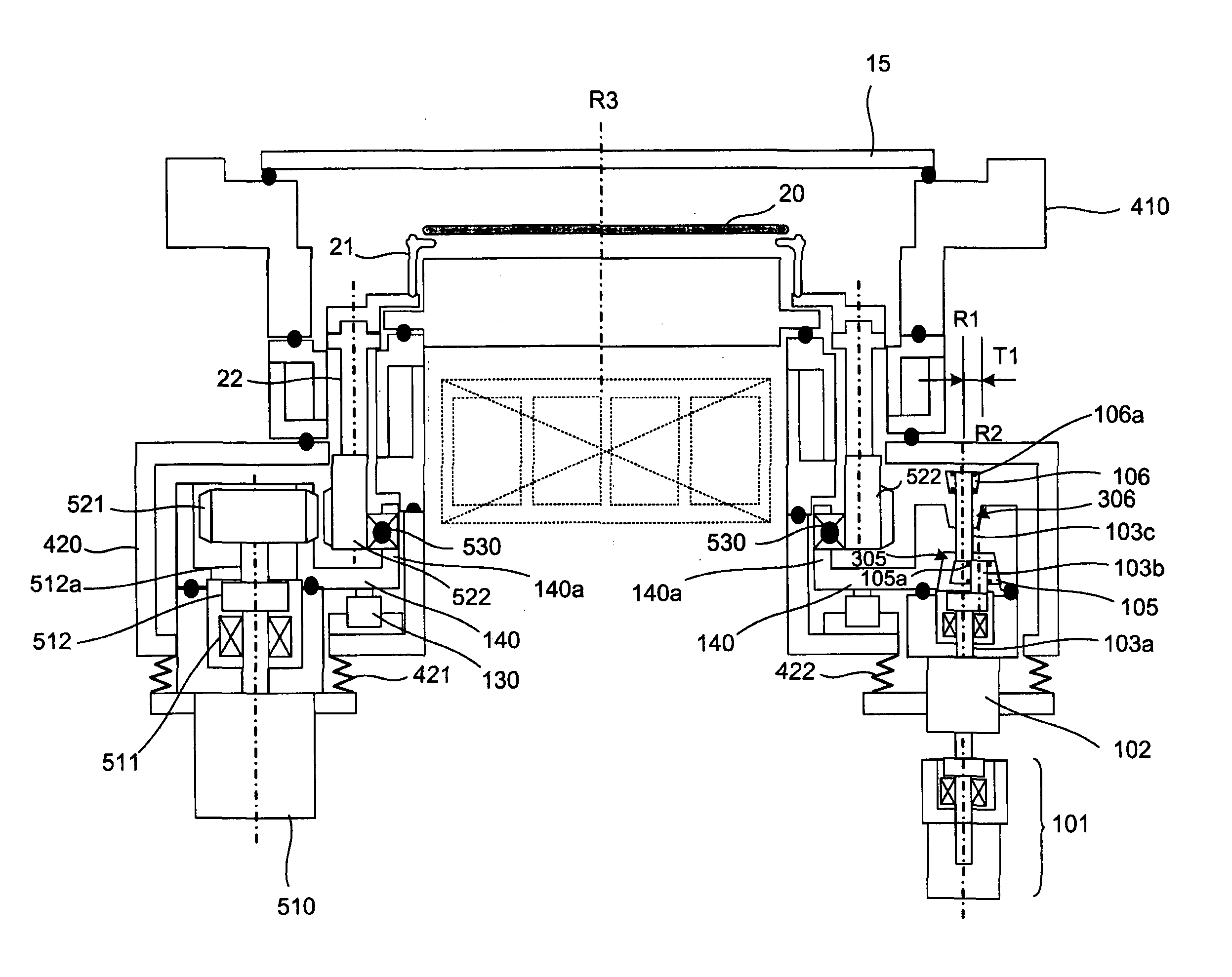
[0034]FIG. 4 shows a substrate rotating and oscillating apparatus for the RTP according to a first embodiment of the present invention. The present invention is characterized in that a substrate is both horizontally rotated and horizontally oscillated, by horizontally oscillating a mutipole magnet type substrate rotating apparatus granted with a patent as KR Patent No. 523674 (Oct. 18, 2005) filed by the present applicant.

[0035][Substrate Rotating Apparatus]

[0036]The multipole-magnetized magnet type substrate rotating apparatus illustrated in FIG. 4 is already filed by the present applicant and patent-registered as KR Patent No. 523674 (Oct. 18, 2005). Therefore, the substrate rotating apparatus will be briefly explained herein.

[0037]When a rotation motor 510 is rotated, a lower multipole-magneted magnet wheel 511 in connection with a rotational shaft of the rotation motor 510 is rotated horizontall...

embodiment 2

Horizontal Rotation and Horizontal Oscillation Using Maglev Motor

[0070]FIG. 16 is a view illustrating the structure of a substrate rotating and oscillating apparatus for an RTP according to a second embodiment of the present invention.

[0071]The maglev motor is rotated entirely by a magnetic force without requiring the rotation motor 510 as in FIG. 4. The maglev motor is configured in a manner that a rotor 622 of a magnet is mounted in a vacant center space of a stator 621 of an annular form. Since a coil is wound on the stator 621, the rotor 622 rotates in a horizontal position as floated by the magnetic field force generated from the coil. The principle of such a maglev motor is generally known in the art. Here, the rotor 622 is connected to the substrate supporter 21 through the connection member 22.

[0072]The maglev motor is wholly supported by the annular oscillation plate 140, and the oscillation plate 140 is oscillated by the oscillating structure the same as explained in the p...


PUM

PropertyMeasurementUnit
Magnetic fieldaaaaaaaaaa

Abstract

Disclosed is a substrate rotating and oscillating apparatus for a rapid thermal process (RTP), that oscillates an oscillation plate using an oscillation motor moved by an elevating unit. Rotational shafts of the oscillation motor comprise lower and upper center rotational shafts mounted on a central axis of the motor, and an eccentric shaft mounted between the lower and the upper center rotational shafts as deviated from the central axis. An oscillation cam is mounted to the eccentric cam. The oscillation plate has an oscillation hole for inserting the oscillation cam therein. A bearing is mounted between the oscillation cam and the eccentric shaft such that the oscillation cam rotates independently from the eccentric shaft. The oscillation plate supports the whole multipole-magnetized magnetic motor or maglev motor. Accordingly, the substrate can be uniformly heated by both rotating and all-directionally oscillating the substrate.

Description

TECHNICAL FIELD[0001]The present invention relates to a substrate rotating and oscillating apparatus for a rapid thermal process (RTP), and more particularly to a substrate rotating and oscillating apparatus for an RTP, capable of oscillating horizontally a substrate in all directions as well as rotating the substrate.BACKGROUND ART[0002]Generally, in a rapid thermal processing (RTP) device, the most significant factor is a speed for heating up a substrate to a desired temperature. Also, the substrate should be uniformly heated. However, as the size of substrates is increasing, it becomes difficult to achieve the uniform heating. To overcome such a problem, there has been introduced an apparatus that horizontally rotates the substrate during the RTP.[0003]In order to restrain generation of noise, vibration and particles, a maglev motor or a multipole-magnetized magnet has been adopted for the substrate rotating apparatus. However, in spite of trying various substrate rotating method...

Claims


Application Information

Patent Timeline
IPC IPC(8): F27D11/00
CPCH01L21/68764H01L21/68792H01L21/68785H01L21/683H01L21/687H01L21/00H01L21/02
Inventor SHIM, JANG WOOLEE, SANG SEOKCHO, WOON KIHER, JUN
Owner AP SYST INC
Learn More