
Zoom lens and camera with the same

a zoom lens and zoom technology, applied in the field of zoom lenses, can solve the problems of reducing the movable range of the first lens unit, the rotatable angle of the cam barrel, and the optical system does not have a realistic configuration for achieving the reduction of the thickness of the camera and the increase of the zoom ratio, so as to achieve the effect of high zoom ratio, reduced thickness, and easy configuration

Inactive Publication Date: 2010-12-23
CANON KK
View PDF5 Cites 3 Cited by
  • Summary
  • Abstract
  • Description
  • Claims
  • Application Information

AI Technical Summary

Benefits of technology

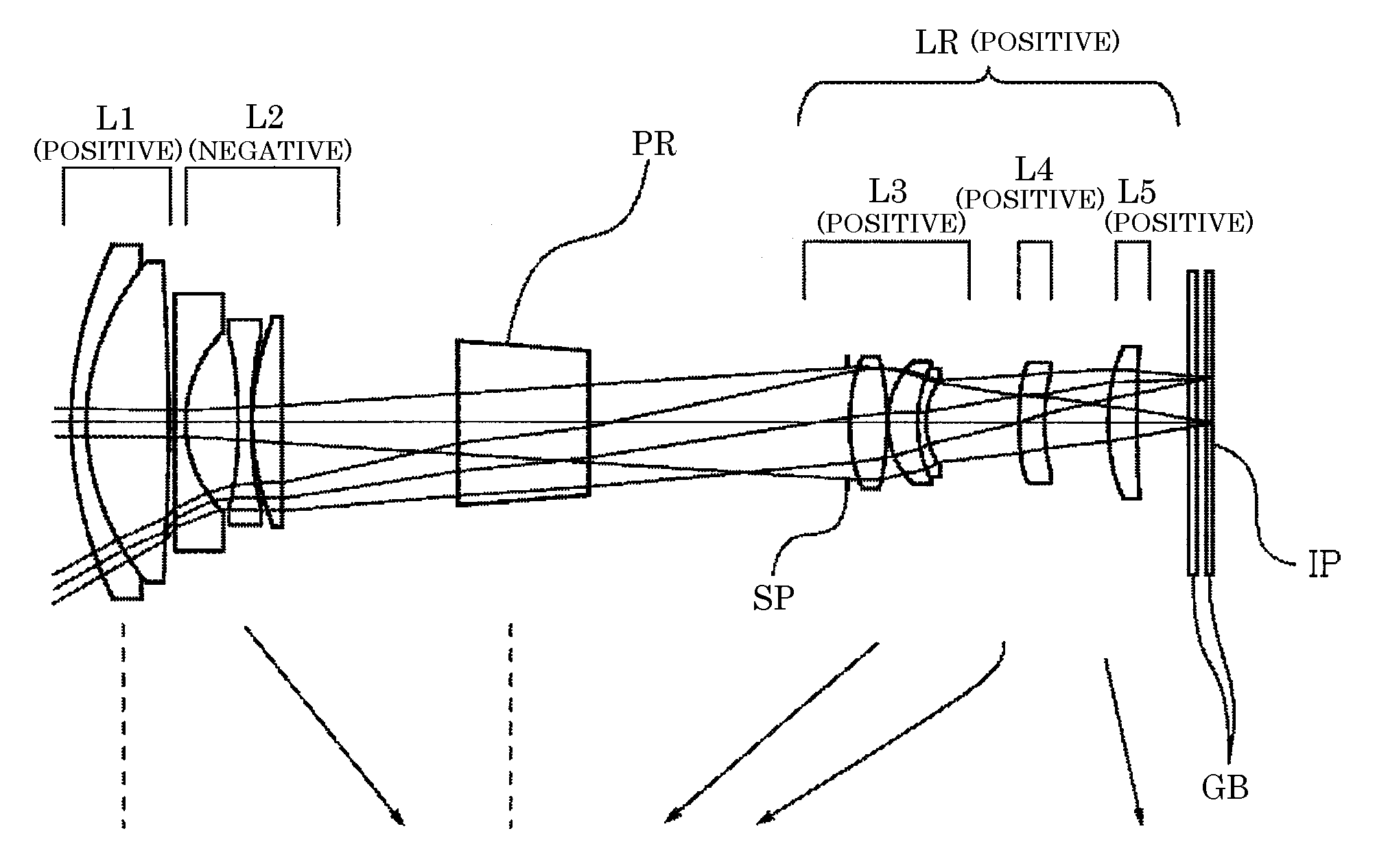
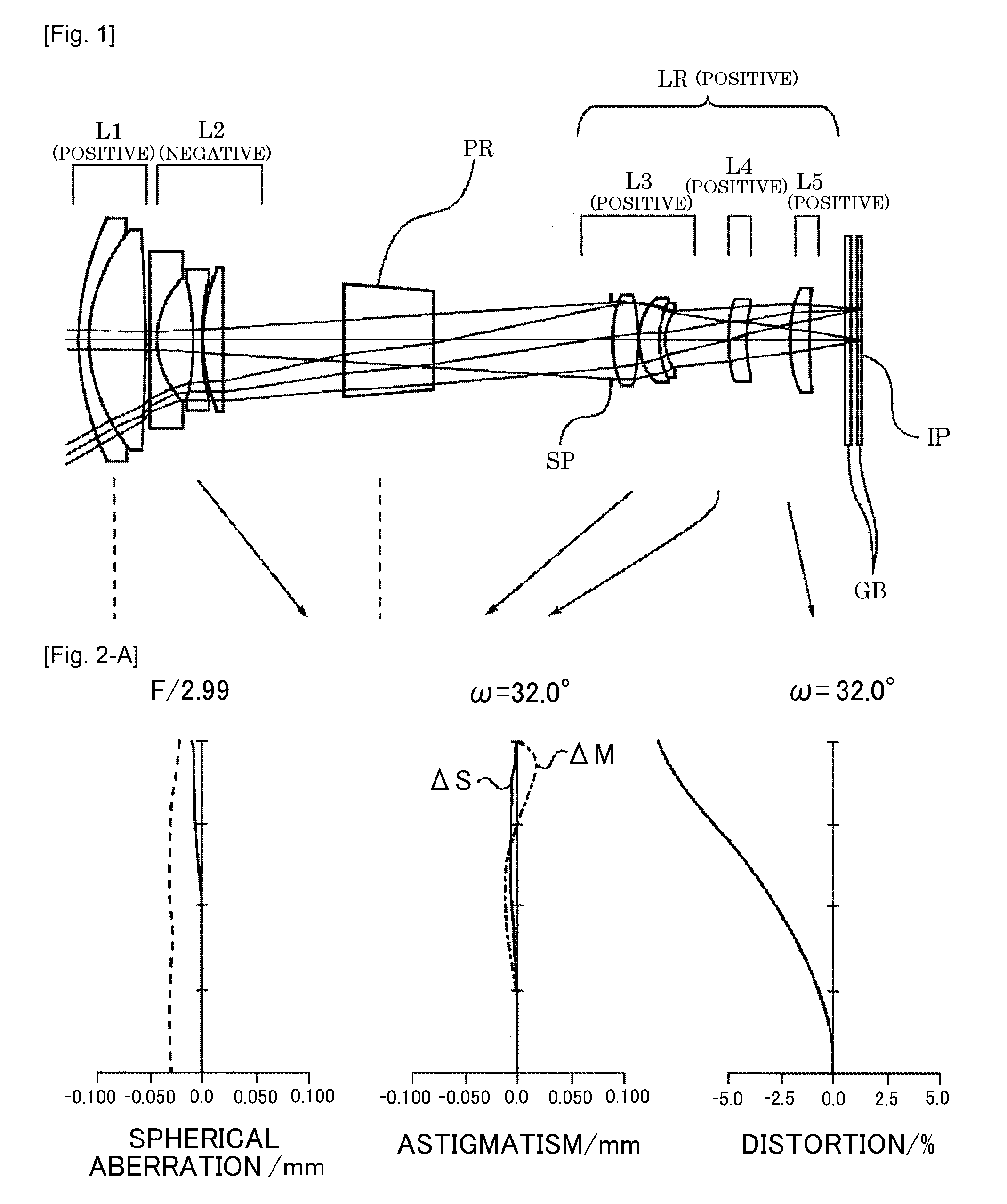
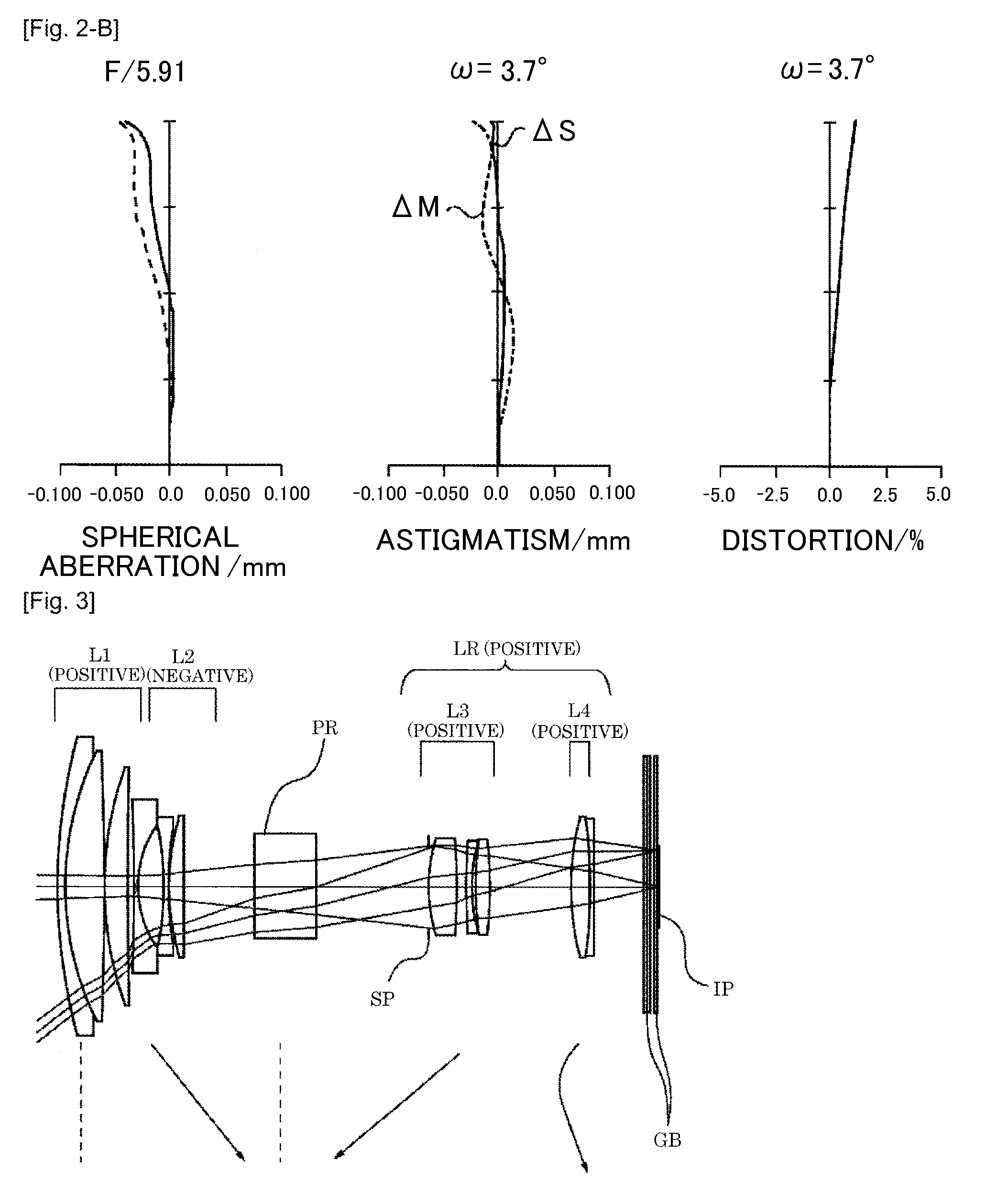
The present invention provides a retractable bent-type zoom lens that can be easily fitted into a camera body. The lens has a high zoom ratio and is thin, making it ideal for portable photography. The lens includes a prism that bends the optical path, and multiple lens units that move during zooming. The first and second lens units can be retracted into a space formed by the movement of the prism, and the overall lens has a positive refractive power. The technical effects of this invention include a compact and portable camera with a high-quality zoom lens that can be easily fitted into a camera body.

Problems solved by technology

However, an optical system disclosed in U.S. Pat. No. 7,426,085 in which a first lens unit disposed closest to the object is moved in a large movable range during zooming is disadvantageous in such a mechanism, so that the optical system does not has a realistic configuration for achieving decrease of the camera thickness and increase of the zoom ratio.
Forming such a large opening on the cam barrel reduces a rotatable angle of the cam barrel, which results in reduction of a movable range of the first lens unit to a range enabling only movement thereof from an image pickup state to a retracted state.

Method used


Image

  • Zoom lens and camera with the same
  • Zoom lens and camera with the same
  • Zoom lens and camera with the same

Examples


numerical example 1

Unit: mm

Surface Data

[0085]

SURFECEEFFECTIVENO.rdndvdDIAMETER 126.2601.201.8466623.824.50 217.0766.161.7130053.921.97 3−110.3880.0520.72 4*−129.136(variable)20.56 5−241.1760.801.8830040.816.88 68.4634.0112.87 7*−27.7401.001.7725049.612.83 8*33.7410.1013.10 918.8232.161.9228618.913.4710609.614(variable)13.3511∞10.00 1.8061033.310.3312∞(variable)9.0913(stop)∞0.107.8914*11.3072.761.4874970.28.0215−26.6180.107.92165.8062.241.4874970.27.50178.3440.602.0033028.36.60185.009(variable)6.011912.4832.111.4874970.27.442015.020(variable)7.3221*14.0932.241.4874970.29.6222147.405(variable)9.3923∞0.601.5163364.120.0024∞0.8020.0025∞0.401.5163364.120.0026∞

Aspheric Surface Data

Surface 4

[0086]K=0.00000e+000 A4=8.82697e−006 A6=−1.32866e−008 A8=3.12115e−011 A10=−1.19317e−013

Surface 7

[0087]K=0.00000e+000 A4=−4.62831e−005 A6=2.61047e−006 A8=−4.58184e−008 A10=3.33447e−010

Surface 8

[0088]K=−2.32869e+001 A4=8.79015e−006 A6=1.71875e−006 A8=−3.59218e−008 A10=1.97760e−010

Surface 14

[0089]K=1.40846e+000 A4=−2.62257e−...

numerical example 2

Unit: mm

Surface Data

[0094]

SURFECEEFFECTIVENO.rdndvdDIAMETER 134.6091.201.8466623.826.00 218.6875.161.5924068.323.30 33414.8900.0522.58 419.8403.201.7725049.620.37 5101.248(variable)19.76 6−243.0640.701.8830040.814.15 77.3973.4210.79 8*−17.7910.701.7725049.610.69 925.4310.0510.801016.2682.041.9228618.911.0011−258.652(variable)10.8712∞8.501.8340037.28.1913∞(variable)7.0914(stop)∞0.007.2415*10.3733.761.6935053.27.5116*−86.3271.747.381750.4990.701.7618226.57.16189.0100.527.001931.8211.771.6127258.77.0120−35.124(variable)7.3221*16.8192.561.6968055.510.9922−32.4960.601.8466623.810.7923−725.734(variable)10.6524∞0.311.5442770.620.9425∞0.501.4940075.020.9426∞0.4020.9427∞0.501.4983165.120.9428∞

Aspheric Surface Data

Surface 8

[0095]K=−7.21881e−001 A4=1.01923e−005 A6=1.60897e−006 A8=−6.61072e−008 A10=1.24904e−009

Surface 15

[0096]K=−3.63771e−001 A4=−5.74951e−005 A6=−4.44172e−007 A8=−1.35331e−008

Surface 16

[0097]K=0.00000e+000 A4=−3.49402e−006 A6=−4.40871e−007 A8=−1.94332e−008

Surface 21

[0098]K=3.6877...

numerical example 3

Unit: mm

Surface Data

[0102]

SURFECEEFFECTIVENO.rdndvdDIAMETER 129.1941.201.8466623.829.90 217.2700.8027.13 319.0506.741.7725049.627.18 4381.695(variable)26.39 5100.4210.901.8596140.317.44 6*8.5224.6813.28 7*−17.0761.351.8830040.813.20 8*272.2460.1113.66 927.5962.181.9228618.914.0710−76.512(variable)14.0511∞9.501.7725049.610.5212∞(variable)9.7513(stop)∞0.108.0814*11.0102.071.4874970.28.3215−28.8330.108.26165.6802.111.5163364.17.82178.3080.602.0033028.36.88184.875(variable)6.151913.5612.081.4874970.26.172017.409(variable)6.1421*15.8712.031.4874970.28.7422226.036(variable)8.5823∞0.601.5163364.120.0024∞0.9020.0025∞0.401.5163364.120.0026∞

Aspheric Surface Data

Surface 6

[0103]K=1.71332e−002 A4=5.30264e−007 A6=−2.58605e−007 A8=9.57676e−009 A10=−2.20369e−010

Surface 7

[0104]K=0.00000e+000 A4=−3.36066e−005 A6=4.41702e−006 A8=−6.19945e−008 A10=2.66086e−010

Surface 8

[0105]K=−4.66725e+003 A4=6.12369e−006 A6=2.48123e−006 A8=−3.56033e−008 A10=1.16071e−010

Surface 14

[0106]K=1.50820e+000 A4=−2.85657e−004 A...


PUM


Abstract

The zoom lens is a retractable bent-type zoom lens capable of providing a high zoom ratio and a reduced thickness, and capable of retracting into a camera body with an easily-configured mechanism. The zoom lens includes in order from an object side to an image side, a first lens unit having a positive refractive power, a second lens unit having a negative refractive power, a prism including a reflective surface, and a posterior lens group which includes plural lens units and has as a whole a positive refractive power. The first and second lens units are retractable into a space formed by movement of the prism in a direction orthogonal to an optical axis of the first lens unit, and, during zooming, the second lens unit and the plural lens units in the posterior lens group are moved while the first lens unit and the prism are fixed.

Description

TECHNICAL FIELD[0001]The present invention relates to a zoom lens suitable for an image pickup optical system used for a camera such as a digital still camera.BACKGROUND ART[0002]A compact zoom lens having a high zoom ratio is requested for an image pickup optical system with increasing performance of cameras (digital cameras) using a solid-state image pickup element.[0003]In order to decrease the size of the camera and increase the zoom ratio of the zoom lens, a so-called retractable zoom lens is widely used in which lens units are disposed closer to each other in a non-image pickup state than in an image pickup state to be retracted into a camera body.[0004]Moreover, U.S. Pat. No. 6,333,823 and Japanese Patent Laid-Open No. 2004-102090 disclose bent-type zoom lenses in which an optical path thereof is bent by 90° using an optical element such as a prism including a reflective surface to reduce a thickness of a camera (hereinafter referred to as “camera thickness”).[0005]Further, U...

Claims


Application Information

Patent Timeline
Patent Type & Authority Applications(United States)
IPC IPC(8): G02B15/14
CPCG02B15/161G02B15/142G02B15/143105
Inventor WADA, KEN
Owner CANON KK
Learn More