
Computationally efficent radar processing method and sytem for SAR and gmti on a slow moving platform

a technology of sar and gmti, which is applied in the field of process and apparatus for generating imagery, can solve the problems of inability to support small platforms generally will not have constant velocity, and require computationally intensive signal processing

Inactive Publication Date: 2010-12-23
UNITED STATES OF AMERICA THE AS REPRESENTED BY THE SEC OF THE ARMY
View PDF0 Cites 54 Cited by
  • Summary
  • Abstract
  • Description
  • Claims
  • Application Information

AI Technical Summary

Problems solved by technology

Current synthetic aperture radar (SAR) algorithms are implemented on platforms that are moving at a constant velocity and at a high speed, and require computationally intensive signal processing.
Small platforms generally will not have constant velocity and cannot support computationally intensive signal processing.
Previously, the problem encountered difficulties due to algorithm complexity, memory limitations, and DSP (computations per second) limitations.

Method used


Image

  • Computationally efficent radar processing method and sytem for  SAR and gmti on a slow moving platform
  • Computationally efficent radar processing method and sytem for  SAR and gmti on a slow moving platform
  • Computationally efficent radar processing method and sytem for  SAR and gmti on a slow moving platform

Examples


Embodiment Construction

[0066]The present invention now will be described more fully hereinafter with reference to the accompanying drawings, in which embodiments of the invention are shown. However, this invention should not be construed as limited to the embodiments set forth herein. Rather, these embodiments are provided so that this disclosure will be thorough and complete, and will fully convey the scope of the invention to those skilled in the art. In the drawings, the dimensions of objects and regions may be exaggerated for clarity. Like numbers refer to like elements throughout. As used herein the term “and / or” includes any and all combinations of one or more of the associated listed items.

[0067]The terminology used herein is for the purpose of describing particular embodiments only and is not intended to limit the full scope of the invention. As used herein, the singular forms “a”, “an” and “the” are intended to include the plural forms as well, unless the context clearly indicates otherwise. It w...


PUM


Abstract

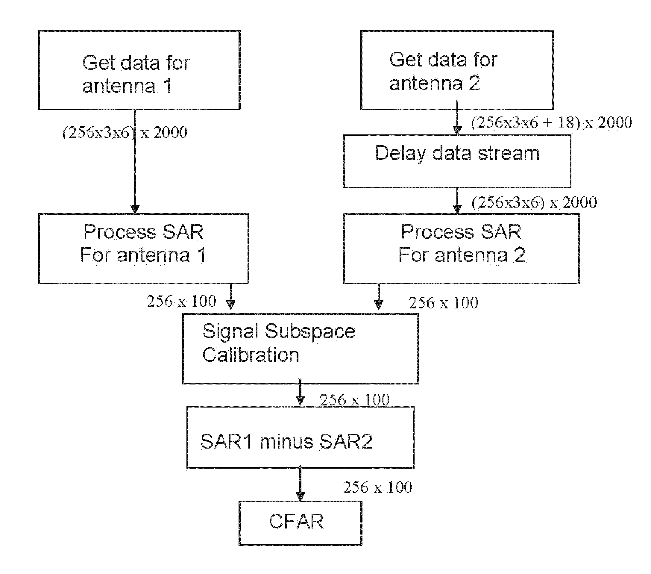
A method and system for processing radar data obtained from a platform which is subjected to non-uniform movement, the distance the platform travels during the formation of an image comprising an aperture; the system comprising software programming for performing a subroutine for building up an average pulse representing a single point on the aperture; the subroutine comprising the steps of inputting radar data from a radar antenna; passing the radar signal through low noise amplifier to reduce impact of electronic noise from the radar system; down converting the signal with a mixer to obtain a lower frequency; filtering out harmonics from the higher frequency range; sampling the radar data using an analog to digital converter at least at Nyquist down range frequency; based upon the IF of the radar; determining a scene center (center of SAR imagery) for the purpose of motion compensation; performing a two stage averaging scheme of the received signals with a variable window function; determining a window function based upon the velocity and acceleration of the platform and scene center; the window function comprising a first stage window; coherently averaging N pulses together to create an average pulse; performing an inverse Fourier transform; compensating to the scene center by multiplying by a complex exponential based upon both the GPS and inertial navigational system; summing the average pulses using low pass filter; the software programming operating to repeat the step of building up an average pulse a first predetermined number of times for a time period that is less than the Nyquist sample time interval; the software programming operating to repeat the step of building an average pulse for a predetermined number of times to generate a second predetermined number of average pulses; the software programming operating to perform a two dimensional inverse Fourier transform to obtain SAR image; outputting the SAR image on a display screen; and a display for displaying the outputted SAR image.

Description

GOVERNMENT INTEREST[0001]The invention described herein may be manufactured, used, and licensed by or for the United States Government.FIELD OF THE INVENTION[0002]The present invention relates in general to a process and apparatus for generating imagery, and in particular to generating imagery using electromagnetic waves.BACKGROUND OF THE INVENTION[0003]Current synthetic aperture radar (SAR) algorithms are implemented on platforms that are moving at a constant velocity and at a high speed, and require computationally intensive signal processing. Small platforms generally will not have constant velocity and cannot support computationally intensive signal processing. There exists a need for an algorithm which overcomes the problems associated with generating a SAR image or a GMTI image on a small unmanned aerial vehicle (UAV), robotic vehicle and / or manned vehicle. Previously, the problem encountered difficulties due to algorithm complexity, memory limitations, and DSP (computations p...

Claims


Application Information

Patent Timeline
Patent Type & Authority Applications(United States)
IPC IPC(8): G01S13/90
CPCG01S13/9029G01S13/9054
Inventor GOLDMAN, GEOFFREY
Owner UNITED STATES OF AMERICA THE AS REPRESENTED BY THE SEC OF THE ARMY
Learn More