Ball paper clip device
a paper clip and ball technology, applied in the field of multi-functional balls, can solve the problems of user inconvenience and low product quality
- Summary
- Abstract
- Description
- Claims
- Application Information
AI Technical Summary
Benefits of technology
Problems solved by technology
Method used
Image
Examples
first embodiment
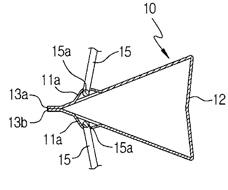
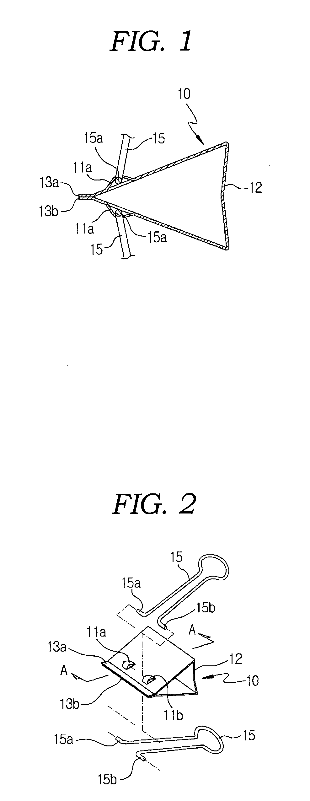
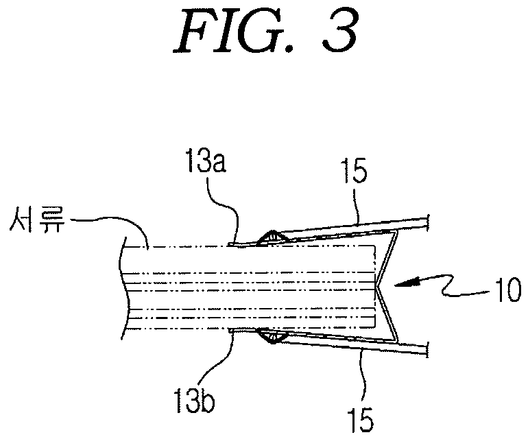
[0021]The first embodiment is illustrated in FIG. 4(a). A ball paper clip 100 includes the upper guide plate 12 and the lower support plate 13 are consist of a bifold shape having a gap 11 made between it. The guide and support plates 12 and 13 are opened at one side thereof to define a gap portion 14 and are connected to each other at the other side. In the clip body 10, the end of the open support plate 13 is taperingly cut to form a taper surface 15, and the guide hole 20 is bored on the guide plate 12 vertically. The clip ball 30 is fitted such that the outer surface thereof may be partially inserted into the guide hole 20. Accordingly, the papers 35 inserted into the gap portion 14 are clamped.
[0022]The clip body 10 includes the guide plate 12 with the guide hole 20 formed therein and the support plate 13 formed integrally with the guide plate 12 at a lower end thereof. The clip body 10's shell can be manufactured in various forms. As shown in FIG. 4, the clip body 10 may have ...
second embodiment
[0026]The second embodiment is illustrated in FIG. 4(b). A ball paper clip 200 includes the upper guide plate 42 and the lower support plate 43 are consist of a bifold shape having a gap 41 made between it. The guide and support plates 42 and 43 are opened at one side thereof to define a gap portion 44 and are connected to each other at the other side. In the clip body 40, the end of the open support plate 43 is taperingly cut to form a taper surface 45. The guide holes 50 bored through the guide plate 42 of the clip body 40 vertically are shaped as symmetrical semicircles and are spaced apart from each other at a certain interval. Also, the pair of clip balls 60 are fitted between the guide plate 42 and the support plate 43 such that outer surfaces of the clip balls may be partially inserted into the pair of guide holes 50, respectively. Accordingly, they cooperate with each other to clamp the paper 35 inserted into the gap portion 44.
[0027]The second embodiment is different from t...
third embodiment
[0031]In the third embodiment, the ball paper clip's side outline's shape maintains ‘S’ which makes people imagine a female figure as shown in FIGS. 4 and 7. The guide hole 80 of the guide plate 72 is formed with curves to emphasize softness. Preferably, the guide hole 80 is formed to decline toward one side from the upper guide's center axis such that one-side surface of the clip ball 90 can protrude to the outside of the clip body 10 when clamping the paper 35. The guide hole 80 is bent with curves, declining toward one side of the clip body 70's center axis. When the paper 35 is inserted into the ball paper clip 300, the clip ball 90 is lifted along the curved guide hole 80. Here, if the clip ball shakes slightly, this structure prevents the clip ball 90 from being lifted arbitrarily along the curved guide hole 80. This shape of the guide hole 80 makes it to firmly clamp papers.
[0032]In addition, when the paper 35 is inserted into the gap portion 74, the clip ball 90 is lifted al...
PUM
 Abstract
Description
Claims
Application Information
 - R&D
- Intellectual Property
- Life Sciences
- Materials
- Tech Scout
- Unparalleled Data Quality
- Higher Quality Content
- 60% Fewer Hallucinations
Browse by: Latest US Patents, China's latest patents, Technical Efficacy Thesaurus, Application Domain, Technology Topic, Popular Technical Reports.
© 2025 PatSnap. All rights reserved.Legal|Privacy policy|Modern Slavery Act Transparency Statement|Sitemap|About US| Contact US: help@patsnap.com


