
On-vehicle communication device

a communication device and vehicle technology, applied in the field of vehicle communication devices, can solve the problems of inability to provide safety support services, inability to receive information normally, congestion in which reliability of communication may decline, etc., and achieve the effect of sufficiently securing transmission power and avoiding congestion

Inactive Publication Date: 2010-12-09
MITSUBISHI ELECTRIC CORP
View PDF7 Cites 70 Cited by
  • Summary
  • Abstract
  • Description
  • Claims
  • Application Information

AI Technical Summary

Benefits of technology

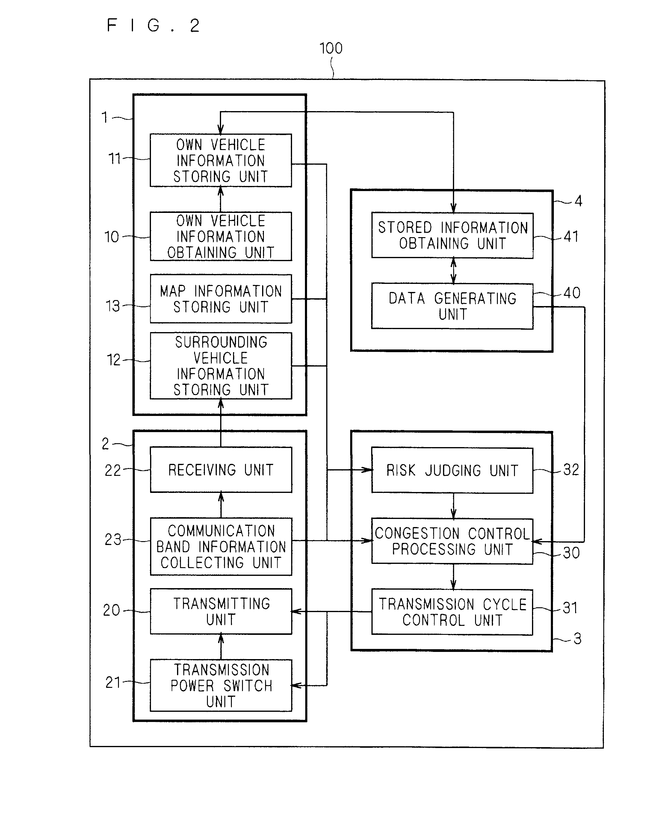
[0014]In the on-vehicle communication device according to Claim 1 of the present invention, the communication control means estimates the first degree of risk and the safe distance using the first vehicle information and the second vehicle information. Further, the communication control means controls the first vehicle transmission cycle based on the first communication channel utilization rate, the second communication channel utilization rate and the first degree of risk, and controls the first vehicle transmission power based on the first communication channel utilization rate, the second communication channel utilization rate and the safe distance.
[0015]Accordingly, it is possible to provide an on-vehicle communication device capable of suppressing a delay in providing information, avoiding congestion, and sufficiently securing transmission power.

Problems solved by technology

CSMA system, vehicles transmit information by themselves. and thus a collision of information occurs when the timings at which information is transmitted are the same, which makes it impossible to receive information normally.
Therefore, it is conceivable that congestion in which reliability of communication deteriorates may occur, and information through inter-vehicle wireless communication is not transmitted without fail, and accordingly safety support service cannot he provided.

Method used


Image

  • On-vehicle communication device
  • On-vehicle communication device
  • On-vehicle communication device

Examples


embodiment

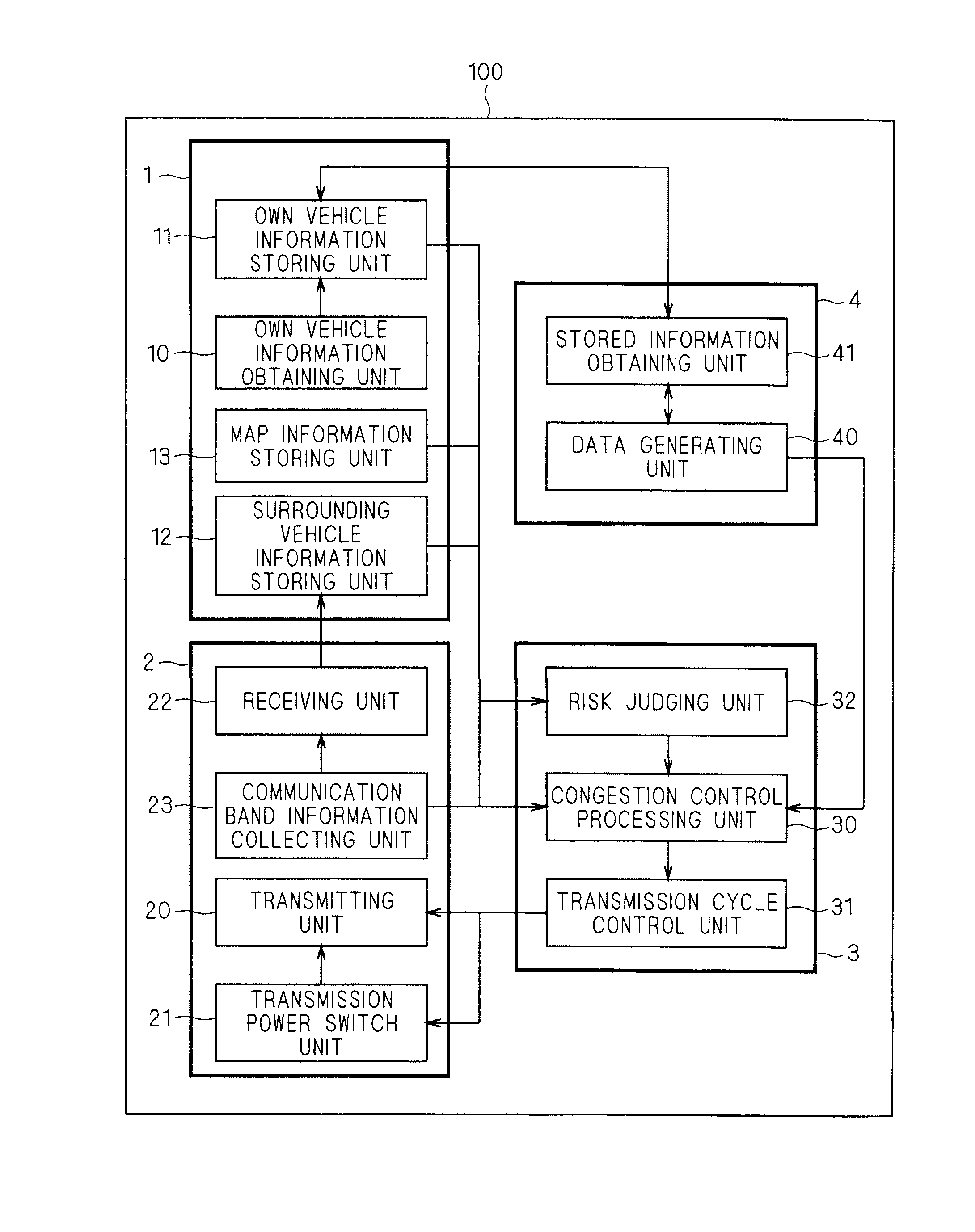
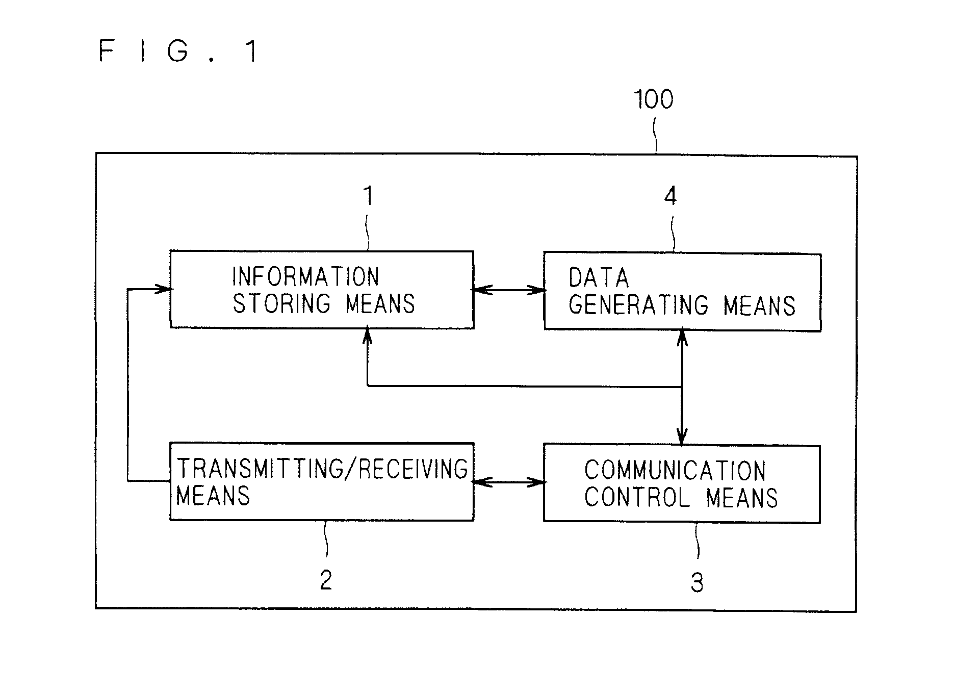
[0032]FIG. 1 is a block diagram showing a configuration of an on-vehicle communication device 100 according to the present embodiment.

[0033]The on-vehicle communication device 100 is mounted on each of a plurality of vehicles. By the on-vehicle communication devices 100, wireless communication is performed between vehicles. Wireless communication herein may employ dedicated short range communication (DSRC) or may employ a protocol used in a local area network (LAN) or a cellular phone.

[0034]Note that the description of the present invention will be given by focusing on one vehicle referred to as “own vehicle” (regarded as a first vehicle) in which the on-vehicle communication device 100 is mounted. In addition, a plurality of vehicles other than “own vehicle”, in which the on-vehicle communication device 100 is mounted, are referred to as “surrounding vehicles” (regarded as second vehicles).

[0035]Referring to FIG. 1, the on-vehicle communication device 100 includes information stori...


PUM


Abstract

The present invention provides an on-vehicle communication device capable of suppressing a delay in providing information, avoiding congestion, and sufficiently securing transmission power. An on-vehicle communication device (100) according to the present invention includes communication control means (3) that controls a transmission cycle and transmission power when data is transmitted from transmitting / receiving means (2). The communication control means (3) uses own vehicle information and surrounding vehicle information to estimate a degree of risk (R) and a safe distance (Ds) of own vehicle. The communication control means (3) controls the transmission cycle of own vehicle based on a communication channel utilization rate of own vehicle, a communication channel utilization rate of a surrounding vehicle and the degree of risk (R) of own vehicle. The communication control means (3) controls the transmission power of own vehicle based on the communication channel utilization rate of own vehicle, the communication channel utilization rate of the surrounding vehicle and the safe distance (Ds).

Description

TECHNICAL FIELD[0001]The present invention relates to an on-vehicle communication device mounted on a vehicle for enabling inter-vehicle wireless communication, and more particularly, to an on-vehicle communication device capable of controlling a mode of the wireless communication based on transmitted / received information.BACKGROUND ART[0002]Recently, commercialization of driving safety support systems utilizing an on-vehicle communication device which performs inter-vehicle wireless communication is being considered. In the on-vehicle communication device, an information exchange application which transmits / receives information of own vehicle per cycle between other vehicles and itself is typically used. Moreover, in the inter-vehicle wireless communication system, a carrier sense multiple access (CSMA) system has been conventionally used as an access system such that each vehicle transmits information by itself.[0003]When an information exchange application is used in the CSMA sys...

Claims


Application Information

Patent Timeline
Patent Type & Authority Applications(United States)
IPC IPC(8): G06F7/00
CPCG08G1/163
Inventor HAMADA, YUJISAWA, YOSHITSUGUGOTO, YUKIOMORITA, SHIGEKI
Owner MITSUBISHI ELECTRIC CORP
Learn More