Pallet assembly process

Inactive Publication Date: 2010-12-09
MILLER DOWEL
View PDF10 Cites 0 Cited by
  • Summary
  • Abstract
  • Description
  • Claims
  • Application Information

AI Technical Summary

Problems solved by technology

Such a pallet can have components that are thinner, smaller in surface area and lower in strength and quality.
In a metal fastener type pallet the components will fall off the pallet when the failure separates the piece from any one metal fastener.

Method used


Image

  • Pallet assembly process
  • Pallet assembly process
  • Pallet assembly process

Examples


Embodiment Construction

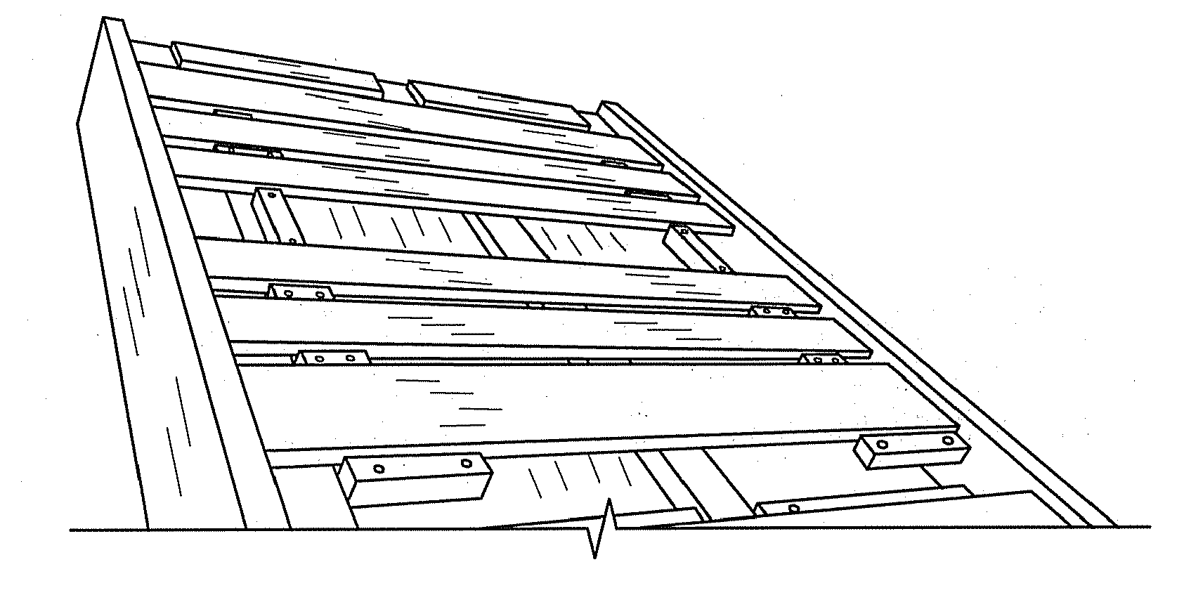
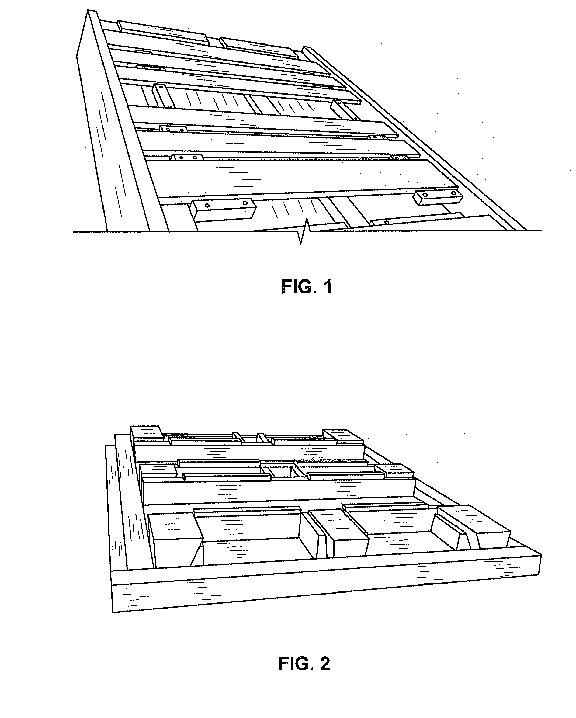
[0012]The subject invention is a process for assembling a block pallet (shown in FIG. 8) by first preparing a ladder assembly and a bottom assembly, and then securing the two assemblies together to form the block pallet.

[0013]The ladder clamp (FIGS. 4 and 5) is used to clamp the assembly called the ladder assembly. The ladder assembly is made of three top stringers and deck boards. The ladder assembly includes top stringers and certain deck boards. The ladder assembly can have other configurations and numbers of deck boards. Subsequently the ladder assembly can be modified to accommodate other configurations where component size, number, configuration, location, type, orientation of grain, and grade vary.

[0014]The bottom clamp (FIG. 7) is used to manufacture the subunit called the bottom assembly. The bottom assembly includes three bottom stringers and two bottom lead boards and nine blocks. One type of block pallet can involve as many as four (4) different types of blocks and each ...


PUM

PropertyMeasurementUnit
Timeaaaaaaaaaa
Timeaaaaaaaaaa
Pressureaaaaaaaaaa

Abstract

A method of manufacturing a wooden pallet secured by glue and dowels is disclosed. The method comprises preparing and arranging the pallet components; drilling dowel holes in the pallet components; applying glue to the dowels and the pallet components; assembling the pallet components to form assembled components; securing the assembled components together with dowels and glue; and clamping the assembled components for a period of time sufficient to allow the glue to cure and form an assembled wooden pallet.

Description

RELATED APPLICATION[0001]This application is related to U.S. provisional application 61 / 149,817, filed Feb. 4, 2009, entitled “PALLET ASSEMBLY PROCESS” which is incorporated by reference herein in its entirety.FIELD OF THE INVENTION[0002]This application relates to pallets, and more particularly to a method for assembling pallets.BACKGROUND OF THE INVENTION[0003]Pallets are used for shipping and warehousing of materials. Glued pallets have a reduced weight due to reduced material component size and number as well as the elimination of typical methods of assembling pallets with metal fasteners, such as nails. Such reduction in the size and weight of pallet components is achieved by the creation of superior joints that are manufactured with glue versus the conventional methods utilizing metal fasteners. The superior joints allow better translation of applied stresses between components, as well as allow superior strength and stiffness. Such a pallet can have components that are thinne...

Claims


Application Information

Patent Timeline
IPC IPC(8): B23P25/00
CPCB65D19/0095B65D2519/00029B65D2519/00064B65D2519/00099B65D2519/00273B65D2519/00293B65D2519/00333B65D2519/00562Y10T29/49885
Inventor TINGLEY, DANIELDUNLAP, KEITHRICHMOND, PAUL
Owner MILLER DOWEL
Why Eureka
Try Eureka