Eureka AIR delivers breakthrough ideas for toughest innovation challenges, trusted by R&D personnel around the world.

Long-range planar sensor array for use in a surgical navigation system

a long-range planar and sensor array technology, applied in the field of magnetic planar sensor arrays for use in surgical navigation systems, can solve the problems of large 3d coils, unwanted x-ray image artifacts, and limited acceptance of surgical navigation systems using these various technologies

Inactive Publication Date: 2010-12-02
GENERAL ELECTRIC CO
View PDF64 Cites 92 Cited by
  • Summary
  • Abstract
  • Description
  • Claims
  • Application Information

AI Technical Summary

Problems solved by technology

Surgical navigation systems using these various technologies are used today with limited acceptance in various clinical applications where an x-ray compatible medical table is used.
A major reason for the limited acceptance of surgical navigation during medical procedures is related to changes required in the normal surgical workflow that complicates the set-up, execution and turn-around time in the operating room.
These navigation system sensors are typically not radiolucent, and if left in the imaging field of view will cause unwanted x-ray image artifacts.
However large 3D coils are bulky, expensive to manufacture, and can potentially interfere with the medical procedure workflow.
However, these planar 2D electromagnetic coil arrays can introduce large ‘dead zones’ or regions of space with large position and orientation errors at specific orientations.
Unless the copper is very thin (approximately less than 0.1 mm), significant attenuation of the x-ray beam will occur, resulting in noticeable image artifacts and reduced image quality.
Unfortunately however, planar 2D electromagnetic coil arrays with thinner copper produces lower magnetic field strengths, resulting in shorter ranges of the electromagnetic sensors.

Method used


Image

  • Long-range planar sensor array for use in a surgical navigation system
  • Long-range planar sensor array for use in a surgical navigation system
  • Long-range planar sensor array for use in a surgical navigation system

Examples


Embodiment Construction

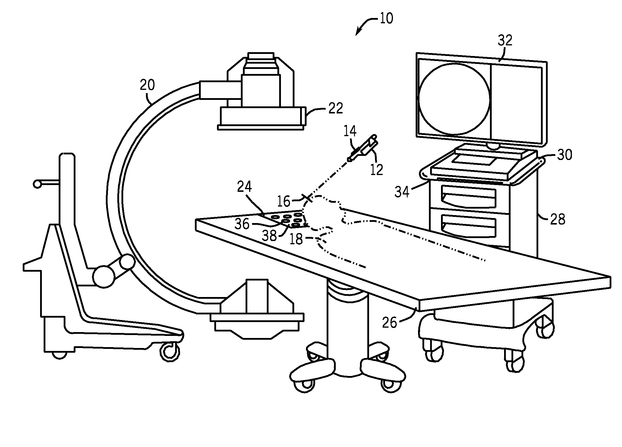
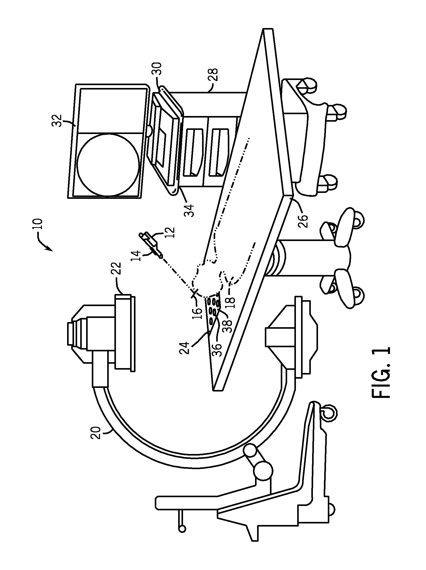
[0024]Referring now to the drawings, FIG. 1 illustrates a schematic diagram of an exemplary embodiment of a surgical navigation system 10. The surgical navigation system 10 includes at least one magnetoresistance sensor 12 attached to at least one device 14, at least one magnetoresistance reference sensor 16 rigidly attached to an anatomical reference of a patient 18 undergoing a medical procedure, a planar sensor array 24 positioned on a table 26 supporting the patient 18, and a portable workstation 28. In an exemplary embodiment, the surgical navigation system 10 may also include an imaging apparatus 20 for performing real time imaging during the medical procedure. In an exemplary embodiment, the imaging apparatus 20 may be a mobile fluoroscopic imaging apparatus. In an exemplary embodiment, at least one magnetoresistance reference sensor 22 may be attached to an imaging apparatus 20. In an exemplary embodiment, the portable workstation 28 may include a computer 30, at least one d...


PUM


Abstract

A planar sensor array for use in a surgical navigation system comprising at least one substrate and at two layers of a plurality of planar sensor coils formed on or within the at least one insulating substrate. The planar sensor array may be an electromagnetic planar transmitter coil array or an electromagnetic planar receiver coil array that includes at two layers of a plurality of planar electromagnetic transmitter or receiver spiral-shaped coils formed on or within the at least one substrate. The surgical navigation system includes the use of at least one magnetoresistance reference sensor attached to a fixed object; at least one magnetoresistance sensor attached to an object being tracked; and a planar sensor coil array communicating with the at least one magnetoresistance reference sensor and the at least one magnetoresistance sensor to determine the position and orientation of the object being tracked.

Description

BACKGROUND OF THE INVENTION[0001]This disclosure relates generally to magnetic sensor arrays for position and orientation determination, and more particularly to long-range magnetic planar sensor arrays for use in surgical navigation systems for determining the position and orientation of an object.[0002]Surgical navigation systems track the precise position and orientation of surgical instruments, implants or other medical devices in relation to multidimensional images of a patient's anatomy. Additionally, surgical navigation systems use visualization tools to provide the surgeon with co-registered views of these surgical instruments, implants or other medical devices with the patient's anatomy.[0003]The multidimensional images may be generated either prior to (pre-operative) or during (intraoperative) the surgical procedure. For example, any suitable medical imaging technique, such as x-ray, computed tomography (CT), magnetic resonance (MR), positron emission tomography (PET), ult...

Claims


Application Information

Patent Timeline
Patent Type & Authority Applications(United States)
IPC IPC(8): A61B5/05
CPCA61B2562/02A61B2562/046A61B2034/2051A61B34/20
Inventor HUBER, WILLIAM HULLINGERLANDBERG DAVIS, CYNTHIA ELIZABETHJENSEN, VERNON THOMAS
Owner GENERAL ELECTRIC CO
Why Eureka
Eureka Blog
Learn More