
Video encoding/decoding apparatus

a technology of video encoding and decoding apparatus, which is applied in the direction of signal generators with optical-mechanical scanning, color television with bandwidth reduction, and signal generators, etc., can solve the problem that filters cannot be designed in accordance, and achieve the effect of reducing errors

Inactive Publication Date: 2010-12-02
KK TOSHIBA
View PDF8 Cites 33 Cited by
  • Summary
  • Abstract
  • Description
  • Claims
  • Application Information

AI Technical Summary

Benefits of technology

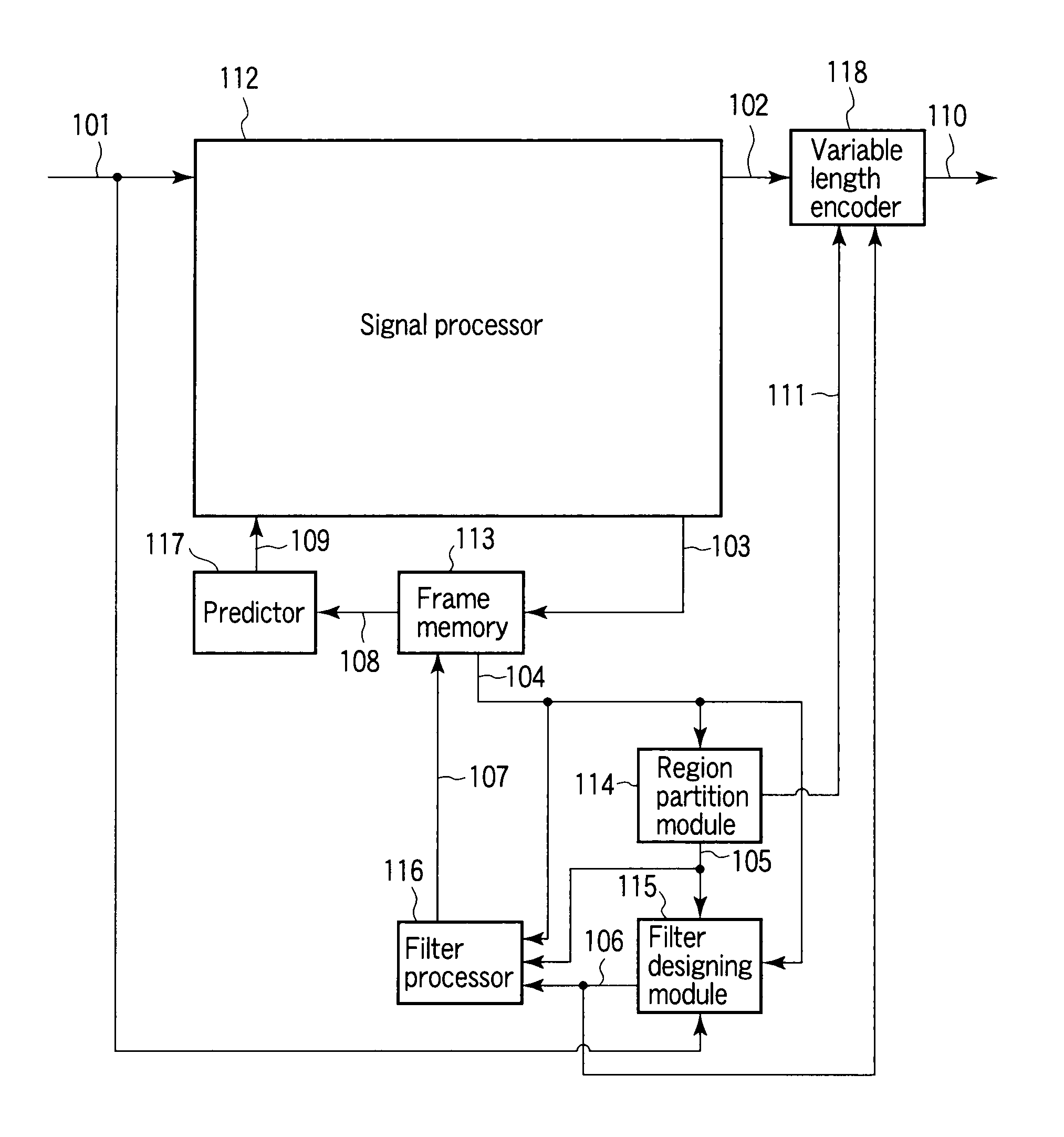
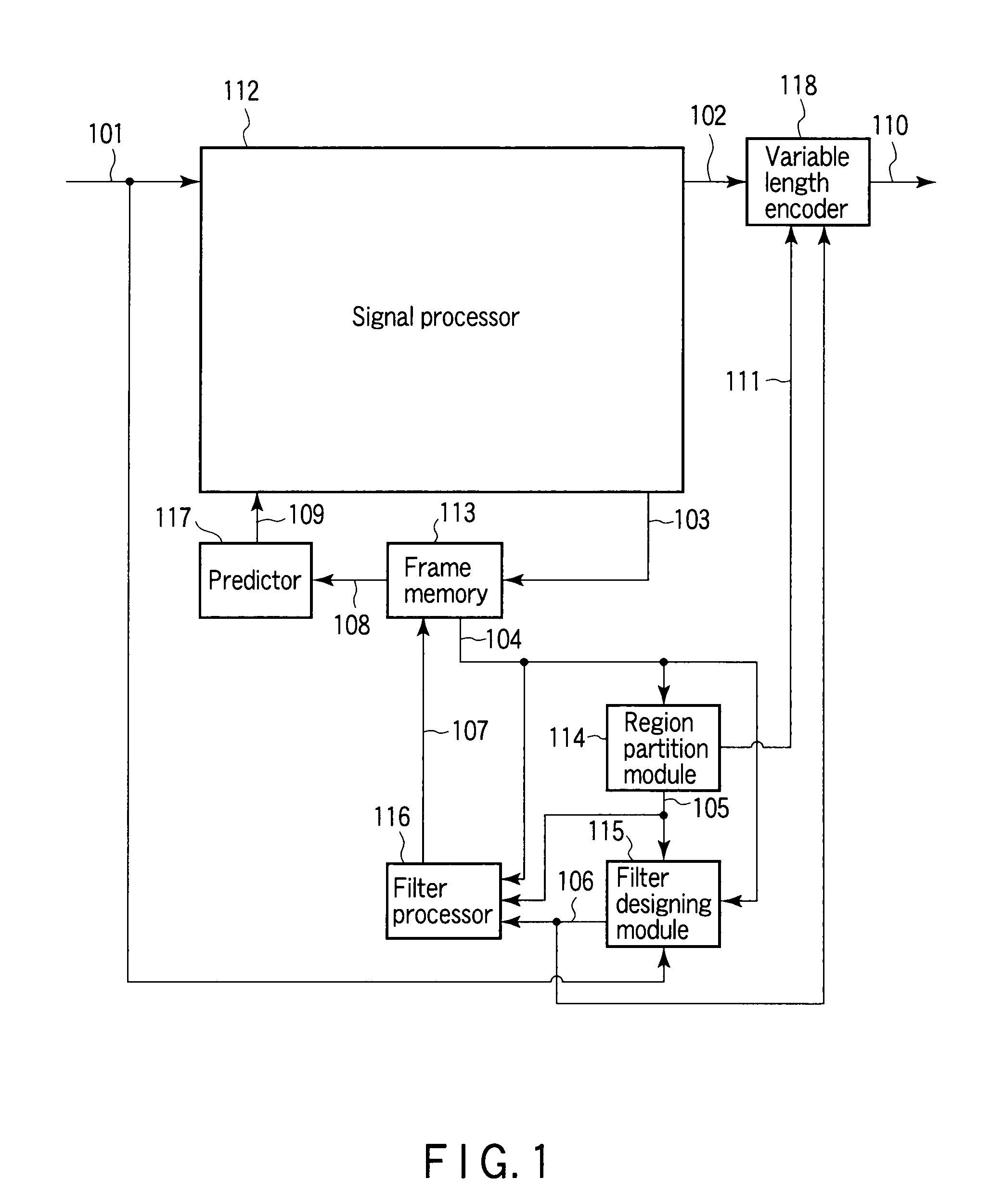
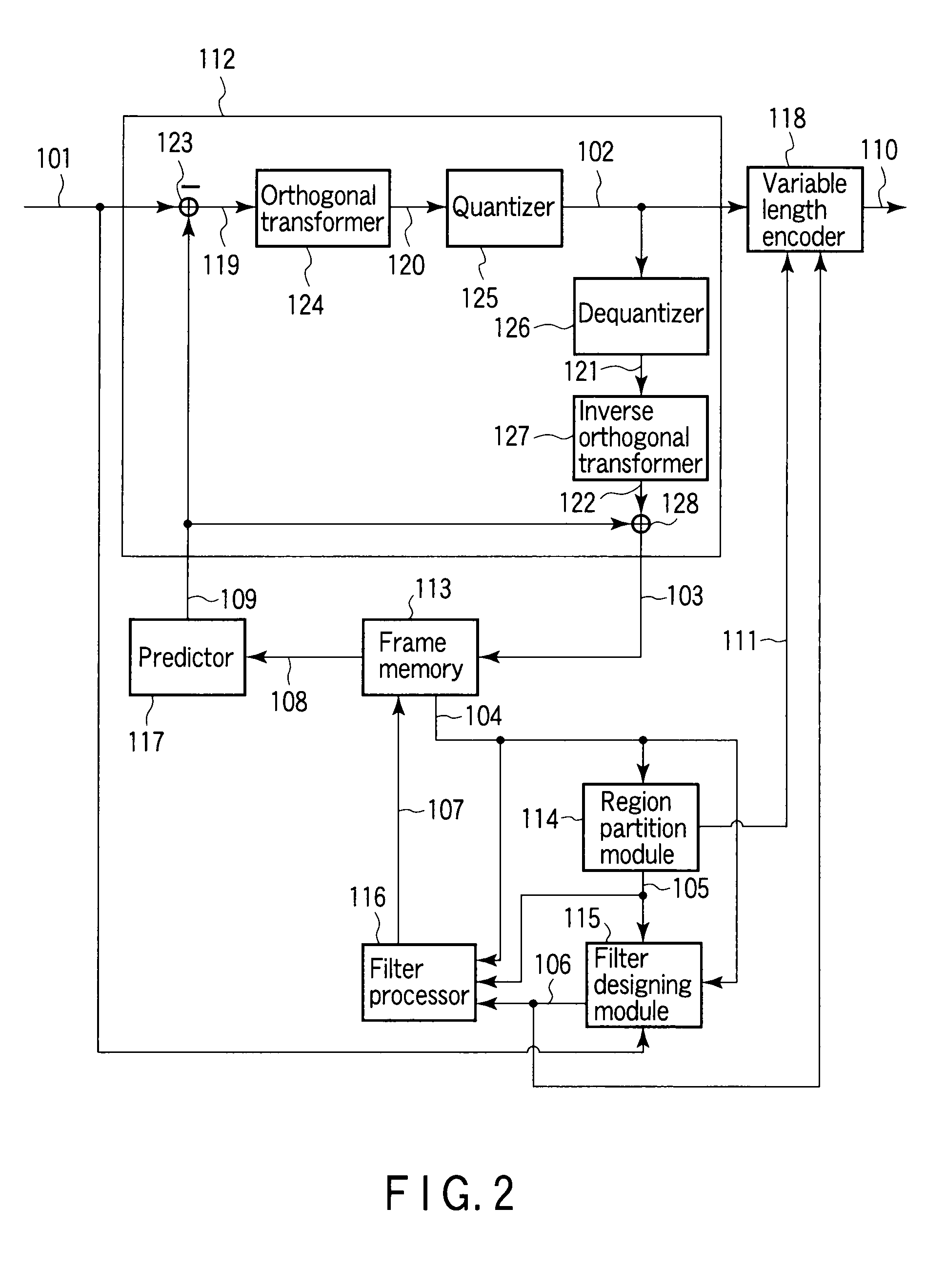
The present invention provides a video encoding / decoding apparatus and method that can classify images into different regions and design filters for each region based on the characteristics of the image. This allows for more precise filtering and reduces errors between the original image and a reference image or an output image. The apparatus includes an image processor, a partition module, a designing module, a filtering module, a storage, a predictor, and an encoder. The technical effect of this invention is to improve video quality and provide a better user experience for viewers.

Problems solved by technology

In a conventional technique, since filters are designed in units of frames, there is a problem that filters cannot be designed in accordance with the characteristics of images which change depending on regions in a frame.

Method used


Image

  • Video encoding/decoding apparatus
  • Video encoding/decoding apparatus
  • Video encoding/decoding apparatus

Examples


tenth embodiment

[0122]A tenth embodiment will be explained. A basic configuration of a video decoding apparatus according to the embodiment is the same as that in the second embodiment shown in FIG. 14. In the embodiment, it is assumed that the filter processor 215 performs the same operation as that of the filter processor 116 according to the ninth embodiment shown in FIG. 24.

eleventh embodiment

[0123]An eleventh embodiment will be explained. A basic configuration of a video encoding apparatus according to the embodiment is the same as that in the third embodiment shown in FIG. 17. In the embodiment, it is assumed that the filter designing module 115 performs the same operation as that of the filter designing module according to the ninth embodiment shown in FIG. 22.

twelfth embodiment

[0124]A twelfth embodiment will be explained. A basic configuration of a video decoding apparatus according to the embodiment is the same as that in the fourth embodiment shown in FIG. 18. In the embodiment, it is assumed that the filter processor 415 performs the same operation as that of the filter processor 116 according to the ninth embodiment shown in FIG. 24.


PUM


Abstract

An image processor to produce a local decoded image corresponding to an input image, a region partitioning module to classify the local decoded image into a plurality of regions using a given parameter, a filter designing module to design a filter coefficient for every classified region, a filter processor to filter the local decoded image according to a corresponding filter coefficient for every classified region, a frame memory to store a filtered image, a predictor to produce a prediction image using a stored image, and an encoder to output a parameter used for classification of the region and information of a filter coefficient every classified region as encoded data are provided.

Description

CROSS-REFERENCE TO RELATED APPLICATIONS[0001]This is a Continuation Application of PCT Application No. PCT / JP2009 / 054186, filed Mar. 5, 2009, which was published under PCT Article 21(2) in Japanese.[0002]This application is based upon and claims the benefit of priority from prior Japanese Patent Applications No. 2008-058374, filed Mar. 7, 2008; and No. 2008-119300, filed Apr. 30, 2008, the entire contents of both of which are incorporated herein by reference.BACKGROUND OF THE INVENTION[0003]1. Field of the Invention[0004]The present invention relates to a video encoding apparatus of adding information for controlling filter processing performed by a video decoding apparatus to encoded data and a video decoding apparatus of performing filter processing on a decoded image based on the information for controlling the filter processing which is added to the encoded data.[0005]2. Description of the Related Art[0006]As a technique for outputting an image obtained by performing filter proc...

Claims


Application Information

Patent Timeline
Patent Type & Authority Applications(United States)
IPC IPC(8): H04N7/12
CPCH04N19/176H04N19/61H04N19/117H04N19/137H04N19/17H04N19/82
Inventor YASUDA, GOKIWADA, NAOFUMIWATANABE, TAKASHITANIZAWA, AKIYUKICHUJOH, TAKESHI
Owner KK TOSHIBA
Learn More