Composite low frequency cutoff filter and imaging apparatus using the same

a low-frequency cutoff filter and composite technology, applied in the field of low-frequency cutoff filters, can solve the problems of large correction residual, inability to obtain phase on the low frequency side of the camera shake correction band to advance, etc., and achieve excellent camera shake correction performance.

Active Publication Date: 2010-12-02
PANASONIC CORP
View PDF2 Cites 3 Cited by
  • Summary
  • Abstract
  • Description
  • Claims
  • Application Information

AI Technical Summary

Benefits of technology

[0009]To solve such problems, a low frequency cutoff filter is provided that can provide the best phase characteristic in a passing band using a simple computation algorithm. In addition, an imaging apparatus is provided that can obtain excellent camera shake correction performance on the low frequency side of a camera shake correction band.
[0012]According to the above aspect, a low frequency cutoff filter that can obtain the best phase characteristic in a passing band using a simple computation algorithm can be implemented by combining a plurality of low frequency cutoff filters. In addition, in an imaging apparatus according to the present invention, the phase fluctuation of a camera shake correction system can be made to be zero on the low frequency side of a camera shake correction band. Thus, there is no phase difference between the actual camera shake and the movement of a camera shake correction lens, enabling to obtain excellent camera shake correction performance.

Problems solved by technology

However, when the integrator has complete integral characteristics even for extremely low frequencies, an extremely low frequency fluctuating component from the angular rate sensor is also amplified and thus excellent camera shake correction performance cannot be obtained.
Such limitation on the integral band of the integrator and the low frequency cutoff filter cause the phase on the low frequency side of the camera shake correction band to advance.
Therefore, the phases of the actual camera shake angle and a correction angle do not match each other, resulting in a large correction residual.
Accordingly, there is a problem that a sufficient suppression effect cannot be secured.
Although there is another method in which the order of the filter is increased to allow the phases to match each other, it has problems, for example, that the increase in the order of the filter complicates a computation algorithm and that a circuit becomes complicated when the filter is configured by hardware.

Method used


Image

  • Composite low frequency cutoff filter and imaging apparatus using the same
  • Composite low frequency cutoff filter and imaging apparatus using the same
  • Composite low frequency cutoff filter and imaging apparatus using the same

Examples


Embodiment Construction

[0026]An embodiment of the present invention will be described below with reference to the accompanying drawings.

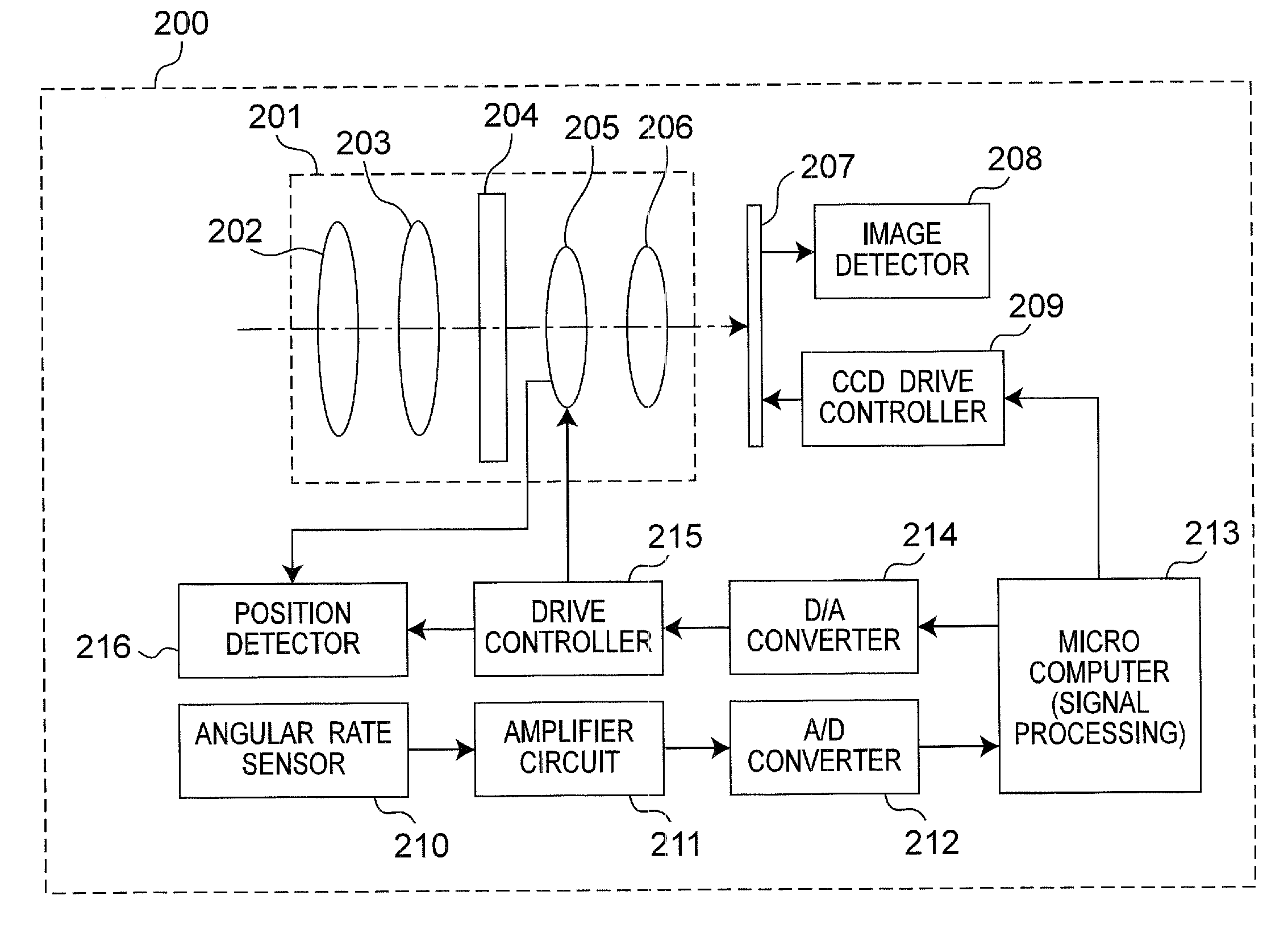
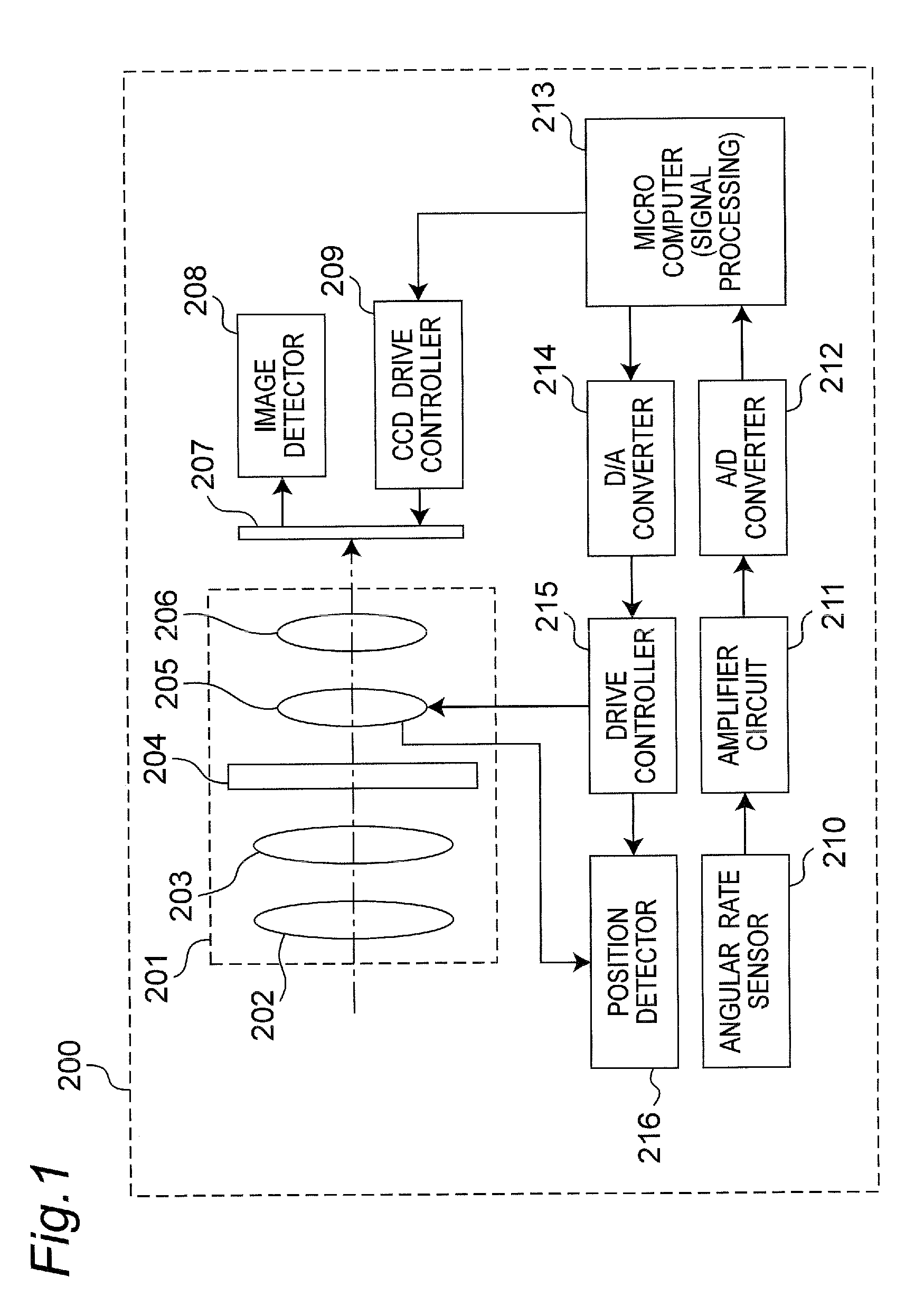
[0027]FIG. 1 is a schematic configuration diagram of an imaging apparatus having a camera shake correction optical system according to the preferred embodiment. An imaging apparatus 200 includes an optical system 201. The optical system 201 includes an objective lens 202, a zoom lens 203, a diaphragm 204, a camera shake correction lens 205, and a focus lens 206.

[0028]The imaging apparatus 200 further includes a CCD (charge-coupled device) 207 that generates image data from an optical signal incident thereon through the optical system 201, an image detector 208, and a CCD drive controller 209 that drives the CCD 207.

[0029]The imaging apparatus 200 further includes an angular rate sensor 210, an amplifier circuit 211 for amplifying an output signal from the angular rate sensor 210, an A / D converter 212 that converts an output signal from the amplifier circuit 211 which is a...


PUM


Abstract

An imaging apparatus includes a composite low frequency cutoff filter. The composite low frequency cutoff filter includes a first low frequency cutoff filter, a second low frequency cutoff filter, and an adder-subtractor. The second low frequency cutoff filter receives an output of the first low frequency cutoff filter. The adder-subtractor subtracts an output of the second low frequency cutoff filter from an input to the composite low frequency cutoff filter, and outputs a result of the subtraction to the first low frequency cutoff filter. An output of the first low frequency cutoff filter is outputted as an output of the composite low frequency cutoff filter.

Description

BACKGROUND[0001]1. Technical Field[0002]The technical field relates to a low frequency cutoff filter which is used for a camera shake correction for an imaging apparatus such as a digital still camera or a digital video camera.[0003]2. Related Art[0004]Some of imaging apparatuses such as digital still cameras and digital video cameras have a camera shake correction function. Such imaging apparatuses have a camera shake correction system (stabilizer) which calculates a camera shake angle by integral of an angular rate detected by an angular rate sensor and drive a correction lens or an imaging device according to the camera shake angle, thereby canceling a camera shake (see, for example, JP2007-324929A). A detection output from the angular rate sensor includes extremely low frequency fluctuating components in addition to components of a camera shake angular rate desired to be detected. Hence, in the camera shake correction system, a low frequency cutoff filter for cutting off a direc...

Claims


Application Information

Patent Timeline
Patent Type & Authority Applications(United States)
IPC IPC(8): H04N5/228H04N5/217G03B5/00H04N5/232
CPCH03H11/04H04N5/23248H04N5/23258H04N5/23287H04N23/68H04N23/6812H04N23/687
Inventor HOSHINO, TAKAYUKI
Owner PANASONIC CORP
Why Eureka
Try Eureka