
Container air handling unit and cooling method

a technology of air handling unit and container air, which is applied in the direction of cooling/ventilation/heating modifications, lighting and heating apparatus, etc., can solve the problems of rack-mounted equipment having adverse effects on the performance, reliability and useful life of equipment components located within the data center, rack-mounted equipment, housed within an enclosure, and being vulnerable to heat build-up and hot spots

Active Publication Date: 2010-12-02
SCHNEIDER ELECTRIC IT CORP
View PDF16 Cites 58 Cited by
  • Summary
  • Abstract
  • Description
  • Claims
  • Application Information

AI Technical Summary

Benefits of technology

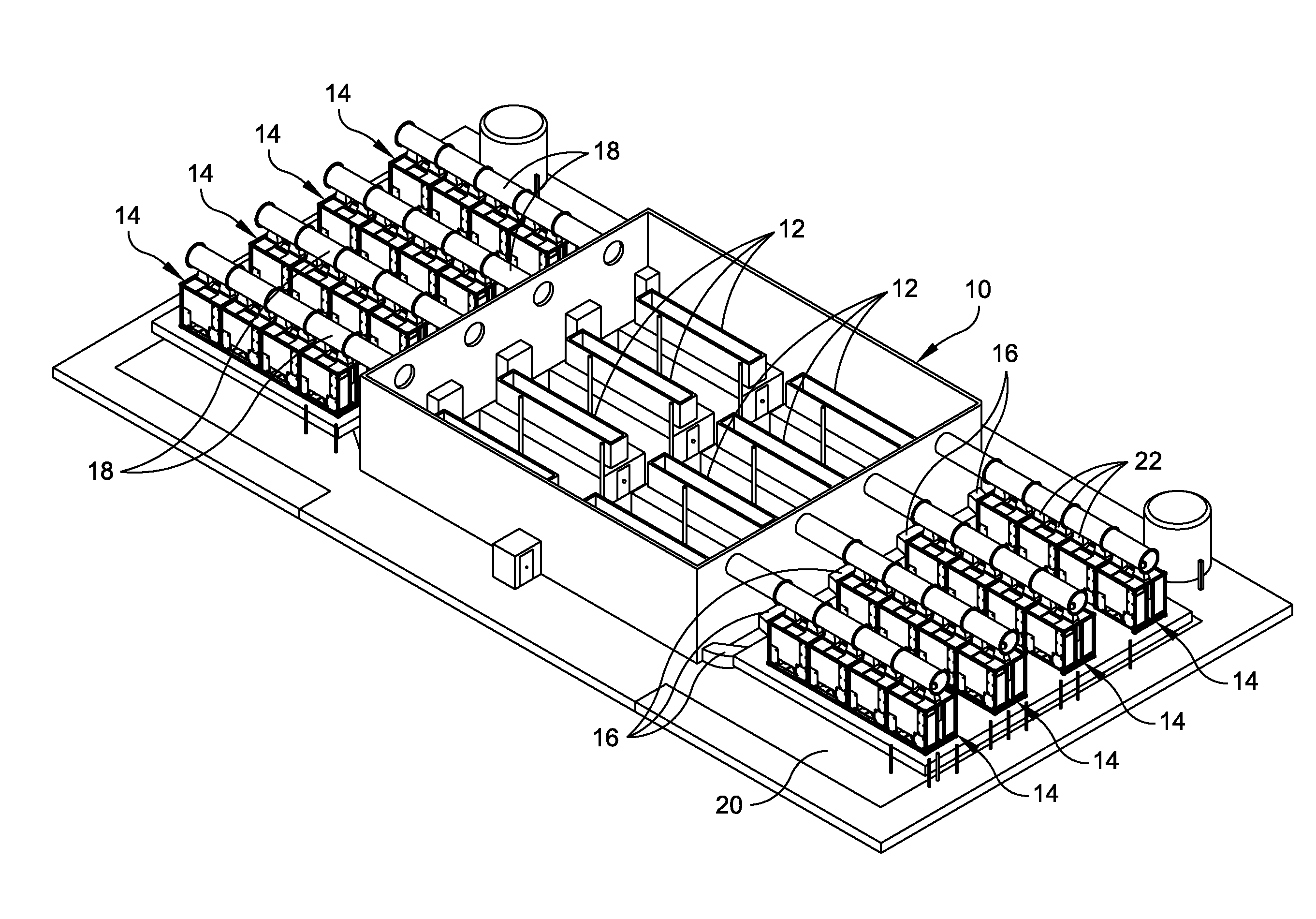
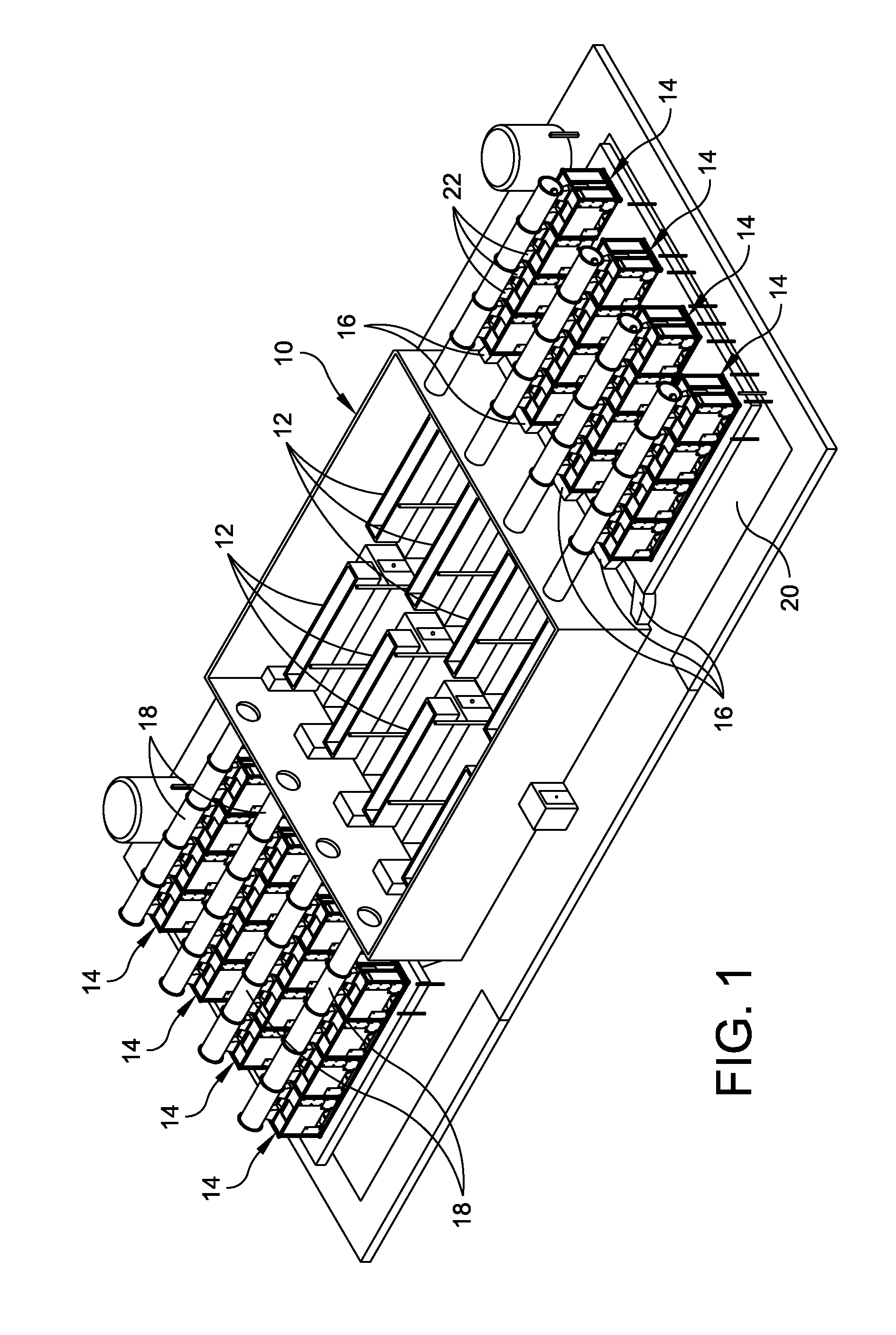
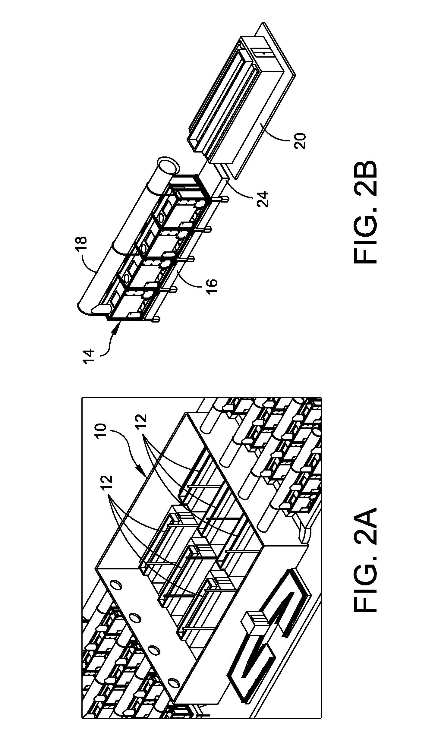
[0007]One aspect of the present disclosure is directed to a modular cooling system configured to treat IT air generated by a data center. In one embodiment, the modular cooling system comprises a frame and a plurality of cooling sub-system modules supported by the frame. The plurality of cooling sub-system modules are configured to operate in parallel to achieve total cooling effect or a lesser cooling effect with some level of redundancy within the data center. In a certain embodiment, each cooling sub-system module comprises a housing configured to support cooling eq

Problems solved by technology

Heat produced by rack-mounted equipment can have adverse effects on the performance, reliability and useful life of the equipment components located within the data center.
In particular, rack-mounted equipment, housed within an enclosure, may be vulnerable to heat build-up and hot spots produced within the confines of the enclosure during operation.

Method used


Image

  • Container air handling unit and cooling method
  • Container air handling unit and cooling method
  • Container air handling unit and cooling method

Examples


Embodiment Construction

[0026]For the purposes of illustration only, and not to limit the generality, the present disclosure will now be described in detail with reference to the accompanying figures. This disclosure is not limited in its application to the details of construction and the arrangement of components set forth in the following description or illustrated in the drawings. The disclosure is capable of other embodiments and of being practiced or being carried out in various ways. Also the phraseology and terminology used herein is for the purpose of description and should not be regarded as limiting. The use of “including,”“comprising,”“having,”“containing,”“involving,” and variations thereof herein, is meant to encompass the items listed thereafter and equivalents thereof as well as additional items.

[0027]The present disclosure is directed to a modular cooling system that is configured to house a plurality of cooling sub-system modules that operate in parallel to achieve total cooling effect or ...


PUM


Abstract

A modular cooling system configured to treat IT air generated by a data center includes a frame and a plurality of cooling sub-system modules supported by the frame. The plurality of cooling sub-system modules are configured to operate in parallel to achieve total cooling effect or a lesser cooling effect with some level of redundancy within the data center. Each cooling sub-system module includes a housing configured to support cooling equipment, an air-to-air heat exchanger supported by the housing to cool IT air generated by the data center, the air-to-air heat exchanger having at least one tube configured to direct IT from one end of the air-to-air heat exchanger to an opposite end of the air-to-air heat exchanger and configured so that outdoor air circulates around the at least one tube, and a mechanical cooling system supported by the housing. The mechanical cooling system is configured to receive IT air treated by the air-to-air heat exchanger and to provide further cooling to the treated IT air. Other embodiments of the cooling system and methods of cooling are further disclosed.

Description

RELATED APPLICATION[0001]This application claims priority under 35 U.S.C. §119(e) to U.S. Provisional Application No. 61 / 183,276, entitled “ISO CONTAINER SUB-BASE WITH ADIABATIC ASSIST AIR ECONOMIZER,” filed Jun. 2, 2009, which is hereby incorporated by reference in its entirety for all purposes.BACKGROUND OF THE DISCLOSURE[0002]1. Field of the Disclosure[0003]Embodiments of this disclosure relate generally to systems and methods for cooling a data center, which houses information technology equipment, such as servers, network switches, data storage and similar devices.[0004]2. Discussion of Related Art[0005]Data centers employing equipment enclosures or racks for housing electronic equipment, such as data processing, networking and telecommunications equipment have been used for many years. Heat produced by rack-mounted equipment can have adverse effects on the performance, reliability and useful life of the equipment components located within the data center. In particular, rack-m...

Claims


Application Information

Patent Timeline
IPC IPC(8): F28F9/00F28D15/00
CPCH05K7/20345H05K7/20827H05K7/20745H05K7/20309H05K7/20318H05K7/20354H05K7/2039
Inventor BEAN, JR., JOHN H.
Owner SCHNEIDER ELECTRIC IT CORP
Learn More