
Stereocopic visualisation

Inactive Publication Date: 2010-11-18
KONINKLIJKE PHILIPS ELECTRONICS NV
View PDF10 Cites 113 Cited by
  • Summary
  • Abstract
  • Description
  • Claims
  • Application Information

AI Technical Summary

Benefits of technology

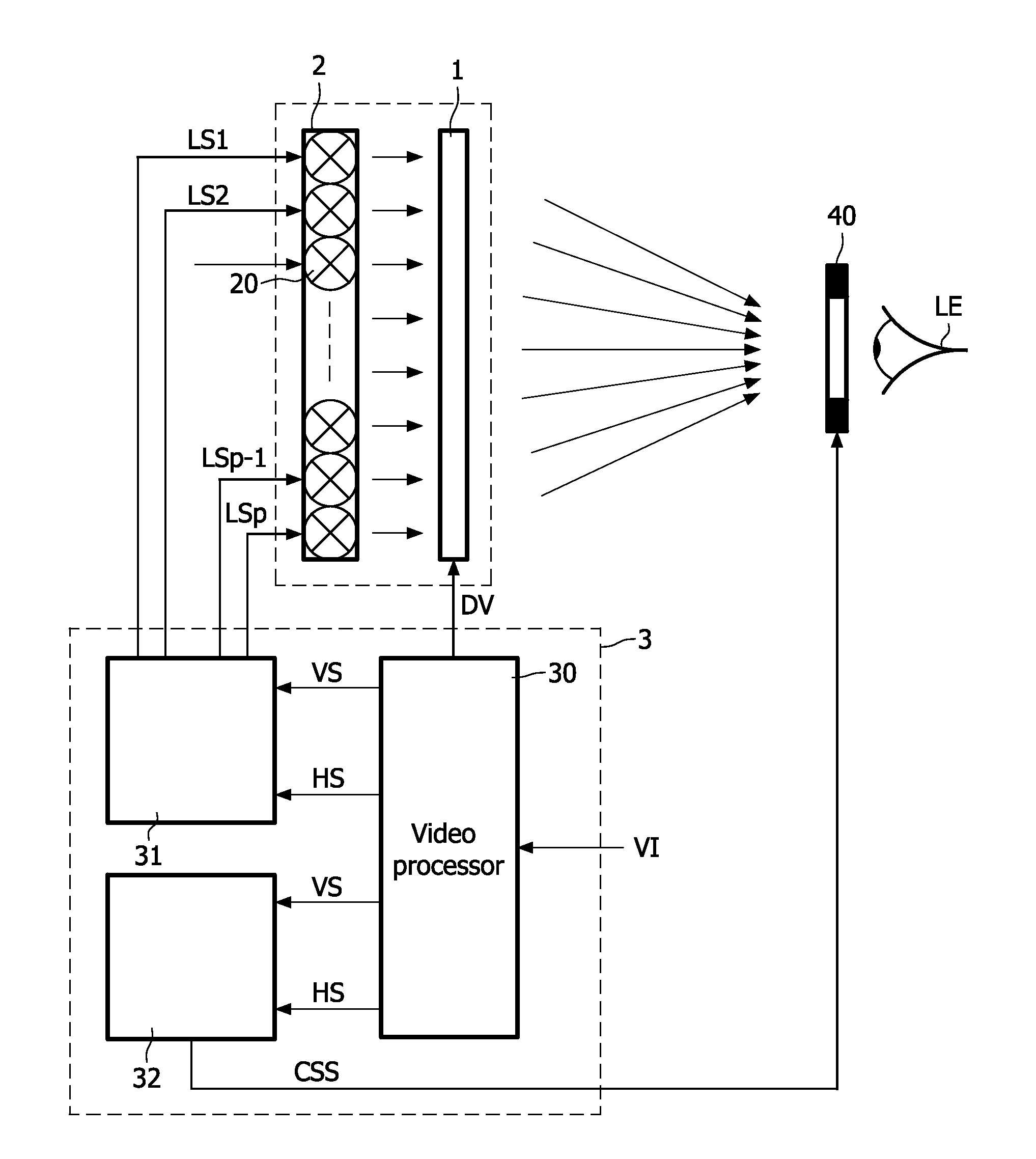
[0011]Further, the controller generates a control signal to control a first one of a pair of 3D shutter glasses to be in a transmissive state to enabling viewing of the pixels of the LC panel or the portion thereof only during the first period in time. If the first image is the left image, the first one of the pair of 3D shutter glasses is the left shutter glass. Thus, the first one of the pair of 3D shutter glasses should be controlled to be in the transmissive state (transmits light to the eye of the observer, this state is also referred to as the on-state) at least during part of the first period in time when the backlight is switched on. Because the switching of the backlight, the first one of the pair of 3D shutter glasses can be in the on-state when the backlight is switched off without the risk of causing crosstalk from the second image. Consequently, the 3D shutter glasses need not switch synchronously with the first period and thus may slowly change their optical state.
[0015]GB2420183 discloses an example of liquid crystal shutter glasses using a LCD. A switched backlight is used to minimize glare from other objects than the LCD screen.
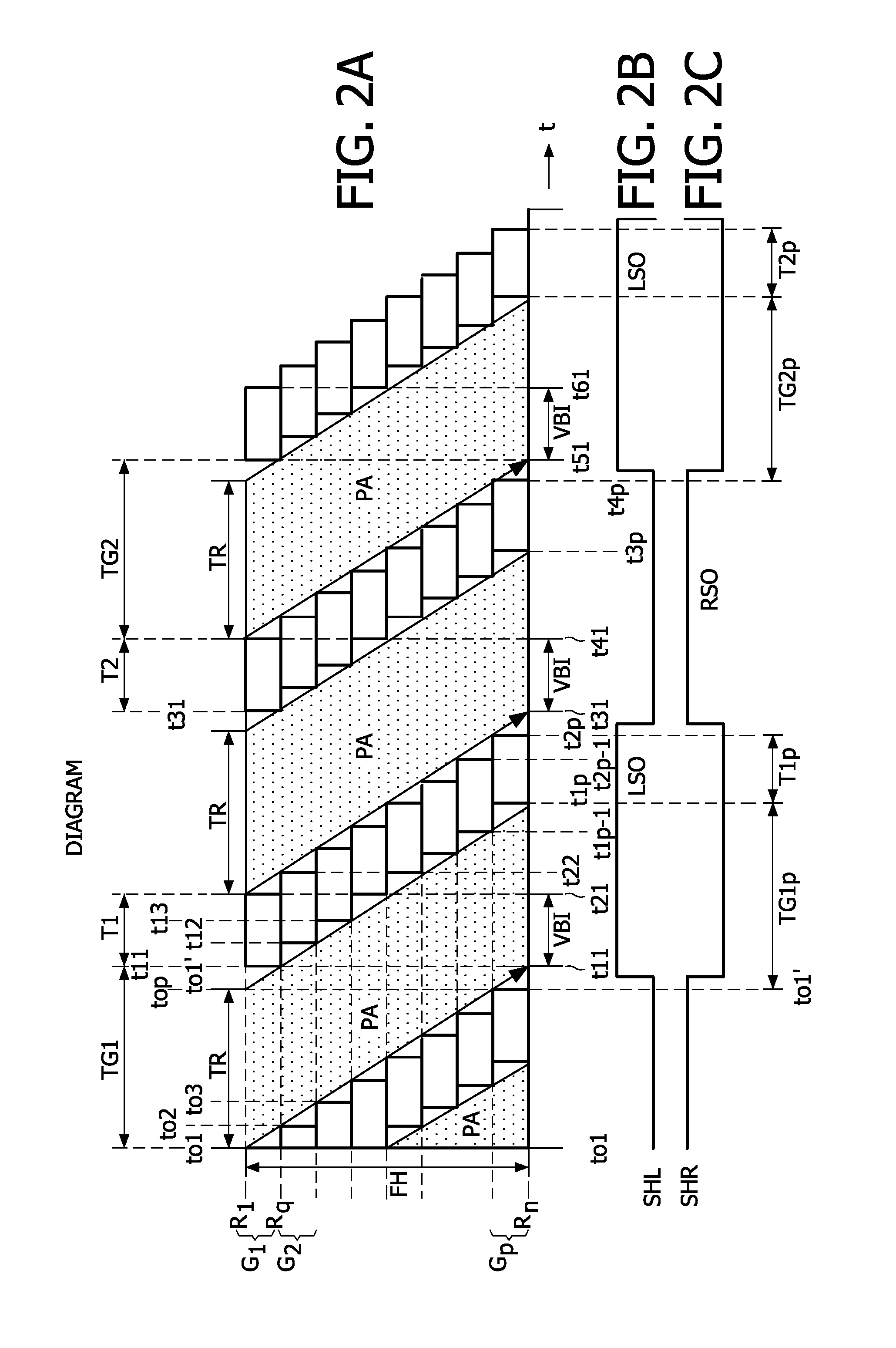
[0020]In an embodiment, the controller generates the transmissive periods such that they have a maximum duration without causing substantial cross talk from the left image to the right eye and the other way around. Because the shutter glasses are non-transmissive during relatively short periods in time only, the average transmitivity is near to 100%. Consequently, the wearer of the shutter glasses is able to see the surroundings with high brightness and without flicker. Further, other viewers wearing shutter glasses do not appear as if wearing sun-glasses and normal eye contact is possible between different viewers wearing shutter glasses.
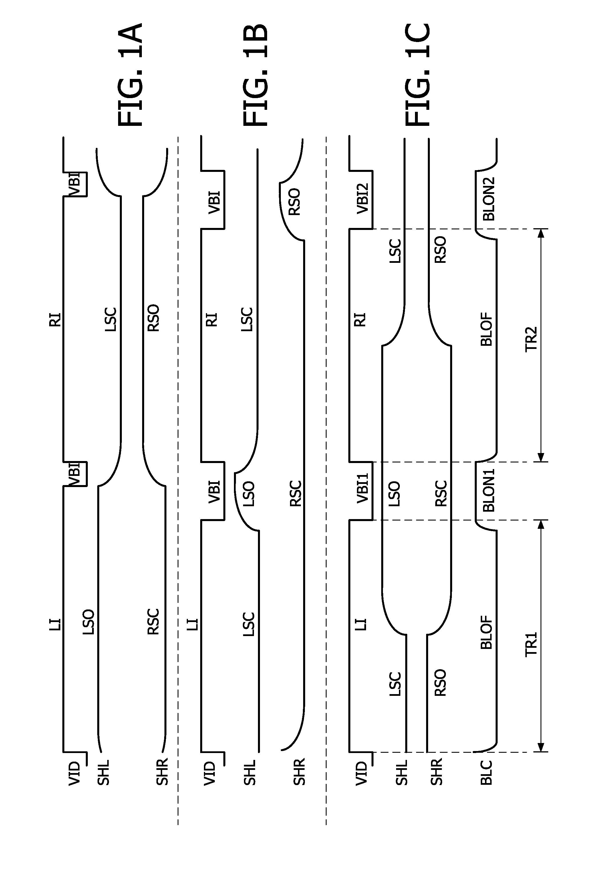
[0022]In an embodiment, the controller generates the first transmissive period and the second transmissive period with 50% duty cycle. This has the advantage that the left and right shutter glasses can be switched as known from the prior art to alternately occlude the left and right eye. The change of state of the glasses occurs in-between the backlight illumination periods, which usually but not necessarily are the vertical blanking intervals. Thus, the glasses may slowly change their optical state without any negative effect during the on-time of the backlight.

Problems solved by technology

However, this approach has the drawback that the LCS 3D glasses have to be switched on for a small period of time only and thus must be fast.

Method used


Image

  • Stereocopic visualisation
  • Stereocopic visualisation
  • Stereocopic visualisation

Examples


Embodiment Construction

[0038]FIGS. 1A to 1C schematically respectively show shutter timings for a CRT, a LCD without pulsed backlight and a LCD with pulsed backlight.

[0039]FIG. 1A shows the known timing of the shutter glasses for a CRT. The top graph stylistically shows the period in time the left image LI is written on the CRT and the period in time the right image RI is displayed on the CRT. The vertical blanking interval in between the left image LI and the right image RI is indicated by VBI. The middle graph shows the optical state of the left shutter SHL. The left shutter SHL is in the transmissive state LSO (the left shutter is open or on) when the left image LI is displayed and in the blocking state LSC (the left shutter is closed or off) when the right image RI is displayed. The bottom graph shows the optical state of the right shutter SHR. The right shutter SHR is in the closed state RSC during display of the left image LI and is in the open state RSO during display of the right image RI.

[0040]Th...


PUM


Abstract

A LCD display system comprises a LC panel (1), a backlight unit (2) for illuminating the LC panel (1) or a portion thereof, and a controller (3). The controller: (i) controls the LC panel (1) to display a first image (LI) and a second image (RI) forming a stereoscopic pair, (ii) controls the backlight unit (2) to only illuminate the LC panel (1) or the portion thereof during a first period in time (BLON1; T1) after the pixels (10) of the LC panel (1) or the portion thereof have a stable optical state according to the first image (LI), and during a second period in time (BLON2; T2) after the pixels (10) of the LC panel (1) or the portion thereof have a stable optical state according to the second image (RI), and (iii) generates a control signal (CSS) for controlling a first one (40) of a pair of 3D shutter glasses (4) to be in a transmissive state for enabling viewing of the pixels (10) of the LC panel (1) or the portion thereof only during the first period in time (BLON1; T1) and a second one (41) of the pair of 3D shutter glasses (4) to be in a transmissive state for enabling viewing of the pixels (10) of the LC panel (1) or the portion thereof only during the second period in time (BLON2; T2).

Description

FIELD OF THE INVENTION[0001]The invention relates to a LCD display system, a method of displaying a stereoscopic image, and a computer program product comprising code for performing the steps of the method.BACKGROUND OF THE INVENTION[0002]The use of a pair of Liquid Crystal Shutter 3D glasses (further referred to as LCS 3D glasses) to view stereoscopic images displayed on Cathode Ray Tubes (further referred to as CRTs) is well known.[0003]The publication “Compatibility of LCD Monitors with Frame-Sequential Stereoscopic 3D Visualisation” of Andrew J. Woods, Ka Lun Yuen, Centre for Marine Science & Technology, Curtin University of Technology, GPO Box U1987, Perth Wash. 6845, Australia, IMID / IDMC '06 Digest, pg. 98-102, 22-25 Aug. 2006, discusses LCS 3D glasses for viewing 3D information on LCD (Liquid Crystal Display) monitors. This publication discloses with respect to FIG. 4 that ghosting could be minimized if the addressing of the LCD panel of the LCD monitor could be sped up. It i...

Claims


Application Information

Patent Timeline
IPC IPC(8): H04N13/04G09G3/36G02B27/22G02B30/25
CPCG09G3/003G09G3/342G09G3/3611G09G2310/024G09G3/36H04N13/0497G02B27/2264G02B27/26G06T15/00H04N13/0438H04N13/332H04N13/341H04N13/398G02B30/24G02B30/25G02B27/017
Inventor GORIS, ROELAND FOCCO EVERHARDREDERT, PETER-ANDRE
Owner KONINKLIJKE PHILIPS ELECTRONICS NV
Learn More