
Systems and methods for aerial cabled transportation

a technology of aerial cabled transportation and system, applied in the direction of transportation and packaging, lighter-than-air aircraft, floating buildings, etc., can solve the problems of energy storage and consumption devices that struggle to perform adequately within the confines of their platform, and achieve high configurable and high speed

Inactive Publication Date: 2010-11-18
WILEY JEREMY A
View PDF14 Cites 15 Cited by
  • Summary
  • Abstract
  • Description
  • Claims
  • Application Information

AI Technical Summary

Benefits of technology

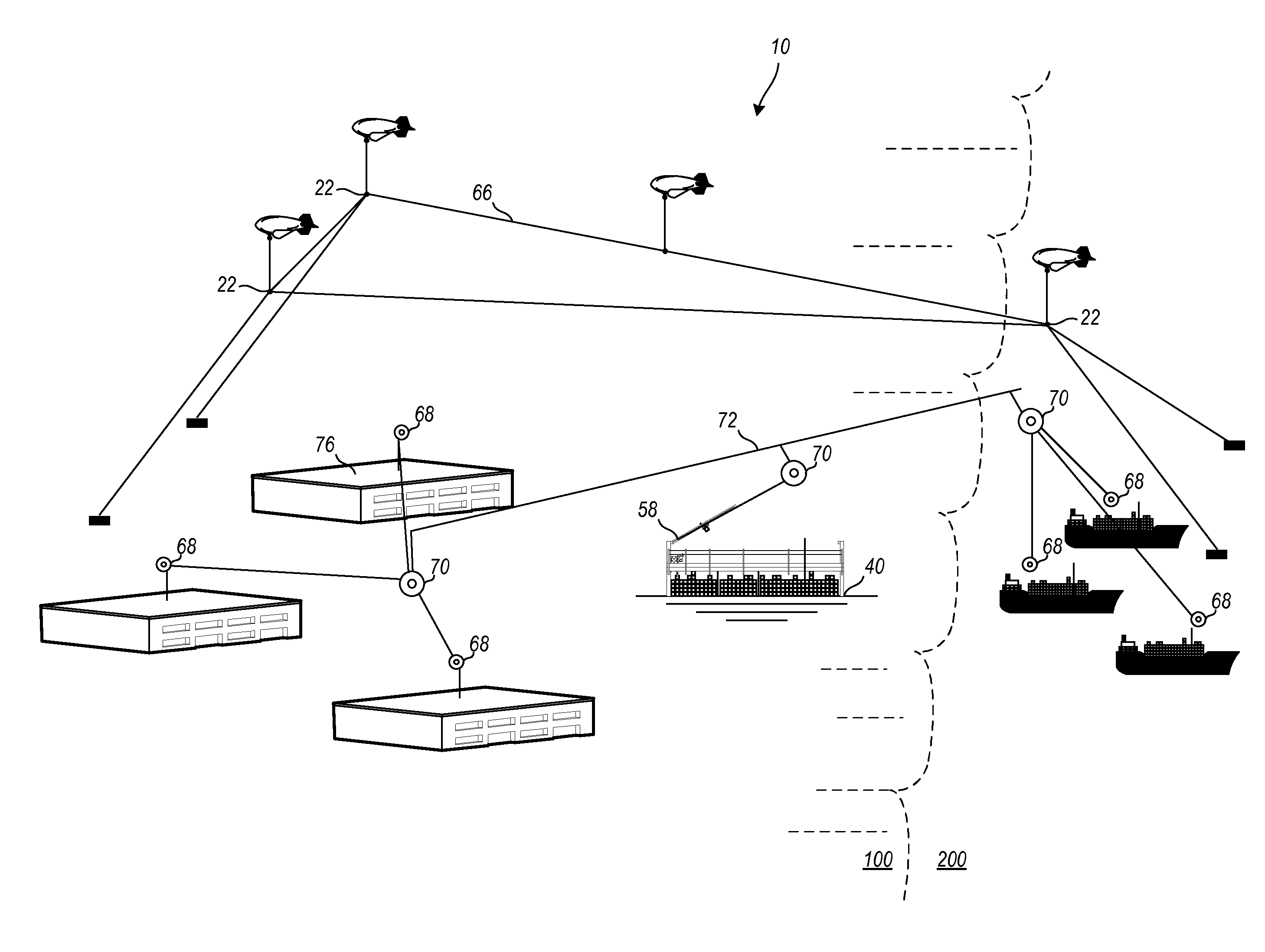
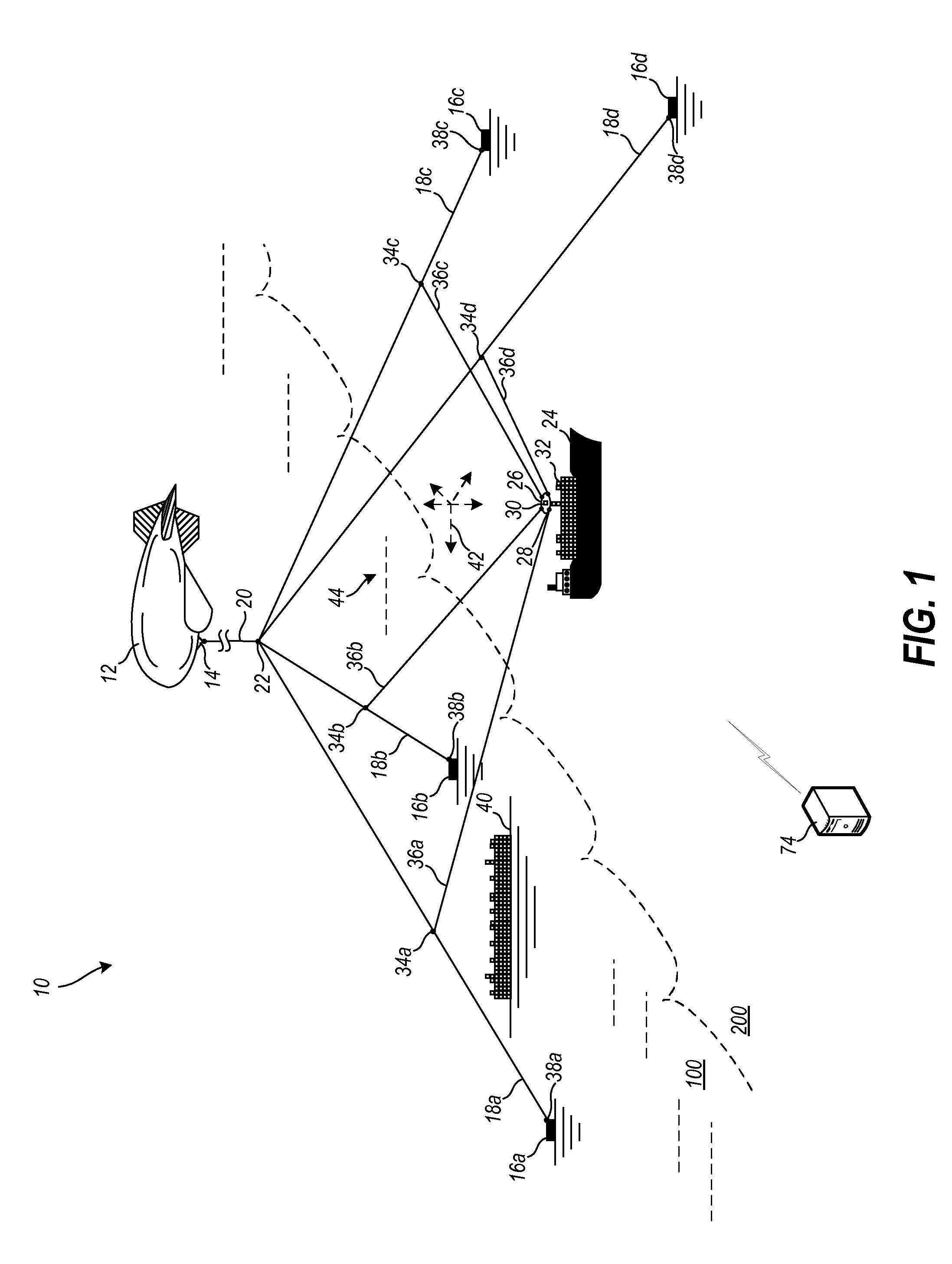
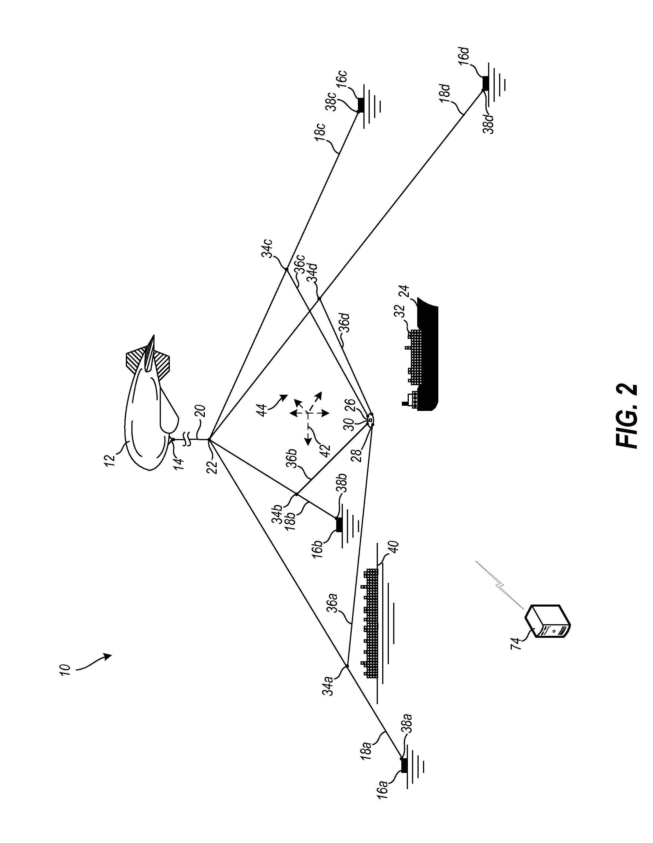
[0011]In various exemplary embodiments, the technology described herein provides for the creation of an atmospherically-lifted multi-tethered structure in a semi-stationary position in the atmosphere, which supports cabled cargo handling operations within the three-dimensional space beneath the structure, allowing cargo loads to move directly from source to destination in that same space (between the ground and the atmospherically-suspended structure itself). The design combines a highly configurable aerial platform with the usefulness of complex cargo transportation systems to enable transit both at high speeds over long distances, and at low speeds on the localized level. Constant atmospheric lift from buoyancy and wind effects allows for a flexible transportation infrastructure over a broad three-dimensional area.
[0012]Highly efficient directly connected mechanically and electrically-powered components are more applicable in this connected infrastructure, whereas in vehicle-based transportation systems, energy storage and consumption devices struggle inefficiently within the confines of their platforms to perform adequately. The consolidation of complex cargo handling systems onto one interconnected, scalable, modular, aerial platform allows for more accessible transportation over both small and large geographical areas by moving cargo over the tops of ground obstacles more directly from origin to destination, supporting more than one load at a time for significantly lower cycle times and higher volumes.
[0023]Each of the anchored guy lines, collectively utilized to anchor the atmospheric lifting devices, connects from one or more ground anchor connectivity points to at least one apex connectivity point, the apex connectivity points connecting through a plurality of cable configurations to each of the atmospheric lifting devices such that the system provides appropriate transportation functionality, to perform multiple payload switching operations and for interconnectivity, while the total amount of suspended cable weight is minimized.
[0033]The method for aerial cabled transportation can also include subsequently raising a plurality of additional atmospheric lifting devices to expand a coverage area of the aerial cabled transportation system; implementing a plurality of subsequent aerial payload support tethers, cargo handling modules, anchored guy lines, pulleys, tension lines, apex connectivity lines, and secondary support tethers; maintaining the plurality of additional atmospheric lifting devices at a plurality of varied heights and a plurality of varied geometric three-dimensional working areas such that a modular, multi-tiered, multi-zone aerial cabled transportation system is erected; and interconnecting the cargo handling modules of various zones to facilitate the transportation of cargo while operating at both a high-speed, long-distance level and a low-speed, localized level.

Problems solved by technology

Highly efficient directly connected mechanically and electrically-powered components are more applicable in this connected infrastructure, whereas in vehicle-based transportation systems, energy storage and consumption devices struggle inefficiently within the confines of their platforms to perform adequately.

Method used


Image

  • Systems and methods for aerial cabled transportation
  • Systems and methods for aerial cabled transportation
  • Systems and methods for aerial cabled transportation

Examples


Embodiment Construction

[0049]Before describing the disclosed embodiments of this technology in detail, it is to be understood that the technology is not limited in its application to the details of the particular arrangement shown here since the technology described is capable of other embodiments. Also, the terminology used herein is for the purpose of description and not of limitation.

[0050]In various exemplary embodiments, the technology described herein provides for the creation of an atmospherically-lifted multi-tethered structure in a semi-stationary position in the atmosphere, which supports cabled cargo handling operations within the three-dimensional space beneath the structure, allowing cargo loads to move directly from source to destination in that same space (between the ground and the atmospherically-suspended structure itself). The design combines a highly configurable aerial platform with the usefulness of complex cargo transportation systems to enable transit both at high speeds over long ...


PUM


Abstract

The technology described herein provides for the creation of an atmospherically-lifted multi-tethered structure in a semi-stationary position in the atmosphere, which supports cabled cargo handling operations within the three-dimensional space beneath the structure, allowing cargo loads to move directly from source to destination in that same space (between the ground and the atmospherically-suspended structure itself). The design combines a highly configurable aerial platform with the usefulness of complex cargo transportation systems to enable transit both at high speeds over long distances, and at low speeds on the localized level. Constant atmospheric lift from buoyancy and wind effects allows for a flexible transportation infrastructure over a broad three-dimensional area.

Description

FIELD OF THE INVENTION[0001]The technology described herein relates generally to the fields of aerostats, cable robotics, tension structures, material handling systems, aerial rail systems, and cargo transportation. More specifically, this technology relates to a cabled apparatus suspended by atmospheric lift as a semi-stationary structure to enable scalable and modular aerial cabled cargo transportation.BACKGROUND OF THE INVENTION[0002]Transportation is a critical part of the entire global economy. However, current ground transportation requires negotiation of significant natural and man-made obstacles occurring along the ground surface in order to transit from a specific source to a specific destination. This requires the creation and maintenance of expansive physical ground infrastructures, including roads, bridges, interchanges, waterways, ports, and a number of other pathways and structures, each having high economic, social and environmental implications.[0003]Although an exte...

Claims


Application Information

Patent Timeline
IPC IPC(8): B64B1/50
CPCB63B35/44B64D3/00B64D1/22B64B1/50
Inventor WILEY, JEREMY A.
Owner WILEY JEREMY A
Learn More