Neck brace

Inactive Publication Date: 2010-11-11
LEATT CHRISTOPHER JAMES +1
View PDF4 Cites 10 Cited by
  • Summary
  • Abstract
  • Description
  • Claims
  • Application Information

AI Technical Summary

Benefits of technology

[0011]The term “stiff” is intended to refer to a body that offers sufficient resistance to deformation, when exposes to a load, to transfer the load. Accordingly, the term includes bodies that are completely rigid an

Problems solved by technology

In the event of a rapid deceleration (e.g. during an accident), the helmeted head tends to move forward relative to the torso and this movement is limited by the tethers.
Neither of these devices offer adequate prot

Method used


Image

  • Neck brace
  • Neck brace
  • Neck brace

Examples


Example

DETAILED DESCRIPTION OF THE DRAWINGS

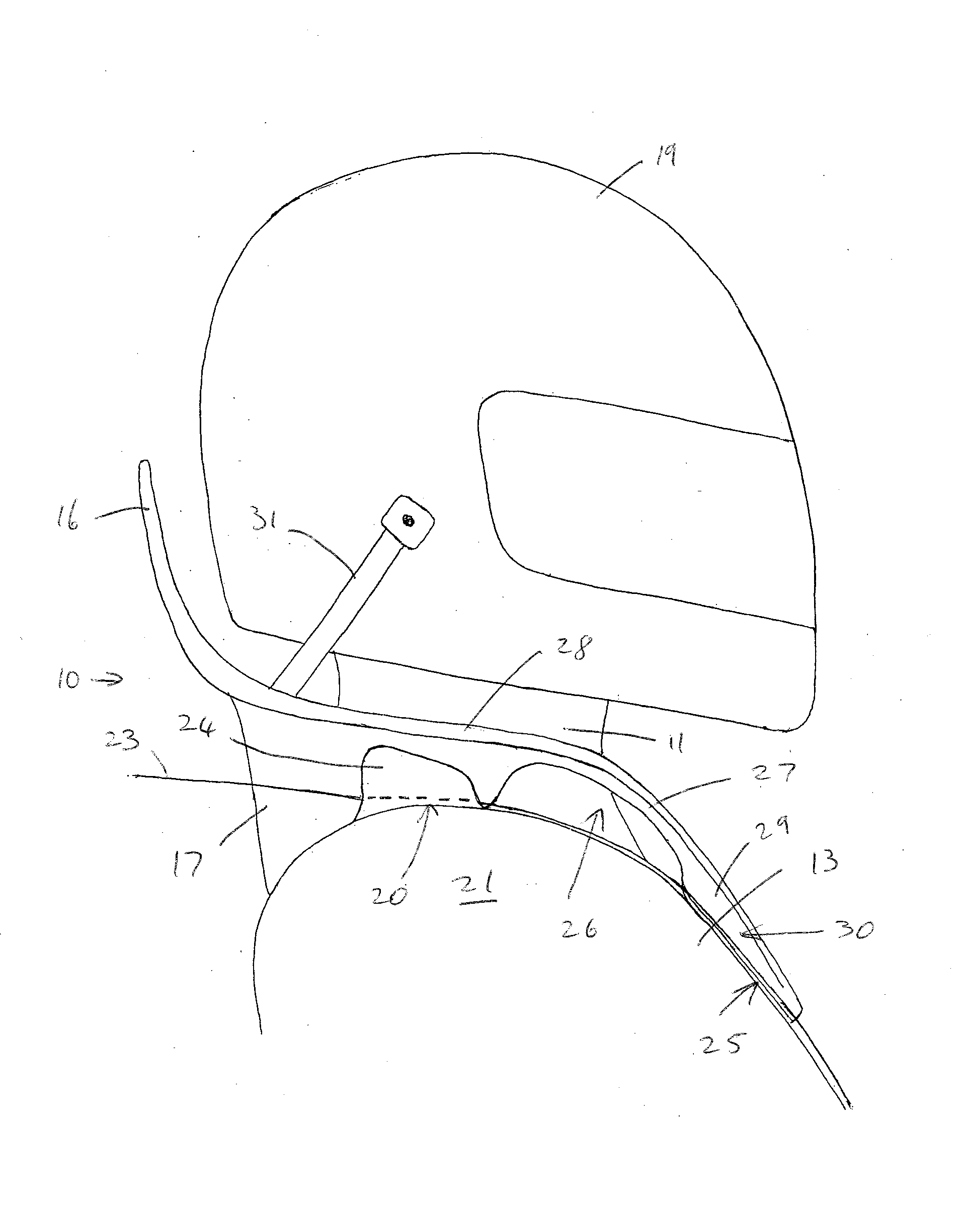
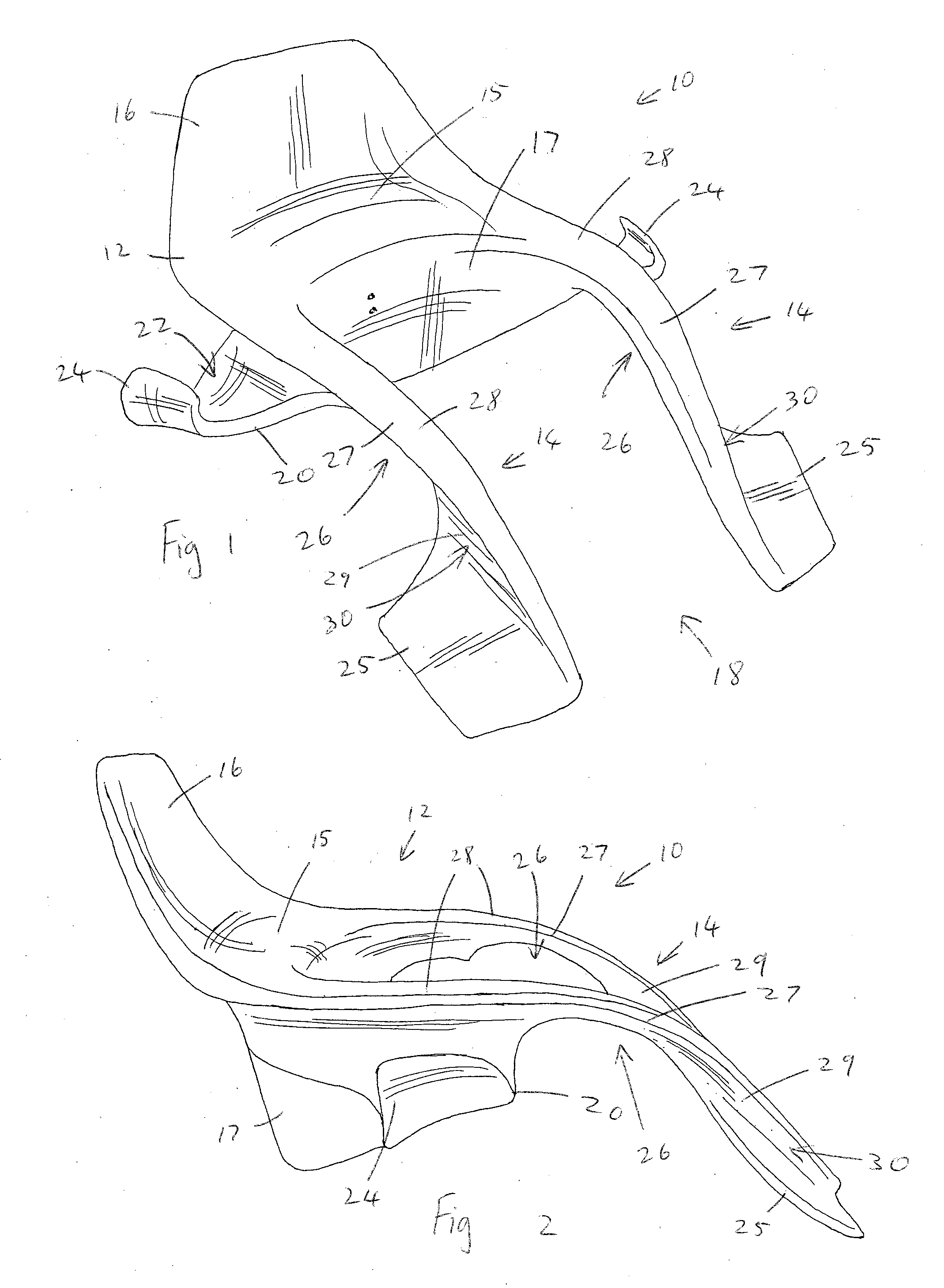
[0019]Referring to the drawings, a neck brace in accordance with the present invention is generally indicated by reference numeral 10

[0020]The neck brace 10 comprises of a body 12 that is generally U-shaped and is made of a stiff material such as a glass reinforced polymer. The body can be fairly rigid, but for the sake of comfort, it should preferably allow a little bit of flexing under bending loads, but it should be stiff enough to transfer impact loads and not be so flexible that it absorbs impact loads by deformation.

[0021]The body 12 has two legs 14 that extend generally parallel on each side of the neck 11 and along the front of the chest 13 of a wearer of the neck brace 10. At the rear ends of the legs 14, they are connected by a bridge formation 17 that extends behind the wearer's neck 11. Above the bridge 17, there is a step formation 15 and above that there is a back wall 16 that extends upwardly behind the wearer's head, but spaced far...


PUM


Abstract

A neck brace has two legs with a gap between them and the legs extend on either side of the wearer's neck and along the front of his torso. Shoulder protuberances, and chest protuberances extending laterally from each leg, are received underneath the shoulder straps of a harness, in the region of the wearer's shoulders and chest, respectively. A recess is defined on an underside of each leg between the shoulder protuberance and the chest protuberance to form a beam that is elevated above the wearer's chest. Each leg and its associated chest protuberance, define a channel in which one of the shoulder straps of the harness is receivable to be held captive.

Description

FIELD OF THE INVENTION[0001]This invention relates to protective gear for preventing injury to the neck and upper cervical spine, when wearing a restraining harness and a helmet. In particular, the invention relates to a head and neck restraint or neck brace.BACKGROUND TO THE INVENTION[0002]A number of neck braces have been developed to be worn by drivers participating in motor racing and similar activities, where the driver is strapped into his seat by a harness, e.g. a four, five or six-point harness, which has shoulder straps extending over the driver's shoulders.[0003]Of these neck braces, presently the most prominent and widely used brace is the HANS (trade mark) device which includes two protuberances that extend underneath the driver's shoulder straps over his chest and extends across the nape of his neck, with an upward protuberance behind his neck and straps or tethers extending from this upward protuberance to his helmet. In the event of a rapid deceleration (e.g. during a...

Claims


Application Information

Patent Timeline
IPC IPC(8): A61F5/00
CPCA41D13/0512A61F5/055A42B3/0473
Inventor LEATT, CHRISTOPHER JAMESHOPKINS, MARK ERIC
Owner LEATT CHRISTOPHER JAMES
Why Eureka
Try Eureka