
Transcranial magnetic stimulation with protection of magnet-adjacent structures

a magnet-adjacent structure and transcranial magnetic stimulation technology, which is applied in the field of transcranial magnetic stimulation with magnet-adjacent structure protection, can solve the problems of not offering a means for restricting the distribution of magnetic field lateral to the target area, undesired side effects such as seizures, and inability to achieve deep brain modulation, etc., to achieve the effect of stimulating the neuronal tissue of the patient, avoiding undesirable side effects in non-target regions,

Inactive Publication Date: 2010-11-11
CERVEL NEUROTECH
View PDF99 Cites 15 Cited by
  • Summary
  • Abstract
  • Description
  • Claims
  • Application Information

AI Technical Summary

Benefits of technology

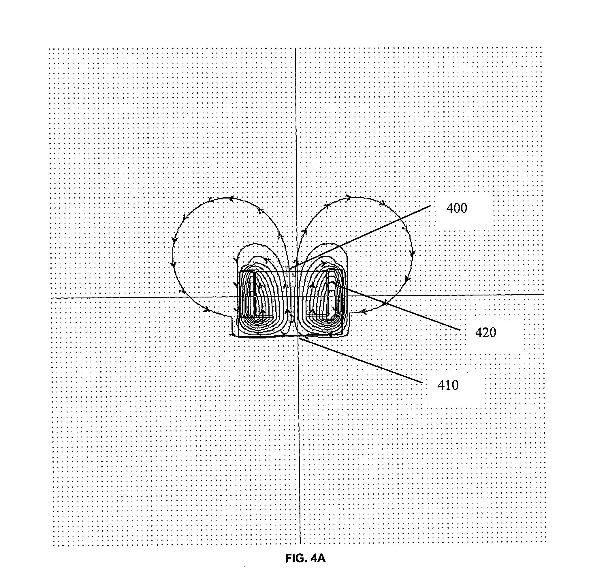
[0011]The shielding enclosure may channel, reflect or attenuate the magnetic field, to prevent the magnetic field from being emitted through the shielding enclosure and into non-target regions adjacent to the TMS electromagnet. Thus, the shielding enclosure may shape the magnetic field. Shielding and shaping of the magnetic field from the TMS electromagnet enables placement of powerful TMS electromagnets in new locations that were previously not usable, due to the pain and involuntary muscular contractions that would otherwise be produced. A shielded enclosure as described herein may allow TMS electromagnets to be used in locations including the interior of mouth or pharynx (e.g., the nasopharyx, laryngopharynx, etc.), making a greater number of trajectories available for use by TMS, while still avoiding problematic trajectories (e.g. to the brain through the eye). These new trajectories include stimulation from the mouth, pharynx, and other inferiorly-located positions in such a way that sensitive adjacent structures are protected from stimulation at levels that provoke undesirable side effects such as painful muscle contractions.
[0015]For example, a Transcranial Magnetic Stimulation (TMS) system for stimulating a patient's neuronal tissue while avoiding undesirable side effects on non-target regions adjacent to the magnet may include: a TMS electromagnet configured to apply Transcranial Magnetic Stimulation to the patient, wherein the TMS electromagnet includes a front face and a back face; and a shielding enclosure for partially enclosing the TMS electromagnet, wherein the shielding enclosure is configured to prevent or limit the emission of a magnetic field into adjacent tissue from the back face of the TMS electromagnet.
[0023]Also described herein are Transcranial Magnetic Stimulation (TMS) systems for stimulating a patient's neuronal tissue while avoiding undesirable side effects on non-target regions adjacent to the magnet that include: a TMS electromagnet configured to apply Transcranial Magnetic Stimulation to the patient, wherein the TMS electromagnet includes a back face and a front face; and a shielding enclosure configured to partially enclose the TMS electromagnet, wherein the shielding enclosure is formed of a high magnetic permeability material, and further wherein the shielding enclosure is configured to modify the magnetic field emitted by the TMS electromagnet to attenuate the magnetic field emitted through the shielding enclosure from the back face of the TMS electromagnet; wherein the shielding enclosure and TMS electromagnet are configured to be combined and placed within a patient's mouth or pharynx.

Problems solved by technology

Deep brain modulation cannot be accomplished by simply turning up the power of the stimulating electromagnet, because the intervening tissue, for example superficial cortex, will be over-stimulated, causing undesired side effects such as seizures.
These techniques typically involve lessening field loops close the coil surface, but do not offer means for restricting the distribution of the magnetic field lateral to the target area.
Also, the cited references do not provide means for limiting the strength of the field radiating from the opposite side of the magnet that faces away from the target.

Method used


Image

  • Transcranial magnetic stimulation with protection of magnet-adjacent structures
  • Transcranial magnetic stimulation with protection of magnet-adjacent structures
  • Transcranial magnetic stimulation with protection of magnet-adjacent structures

Examples


Embodiment Construction

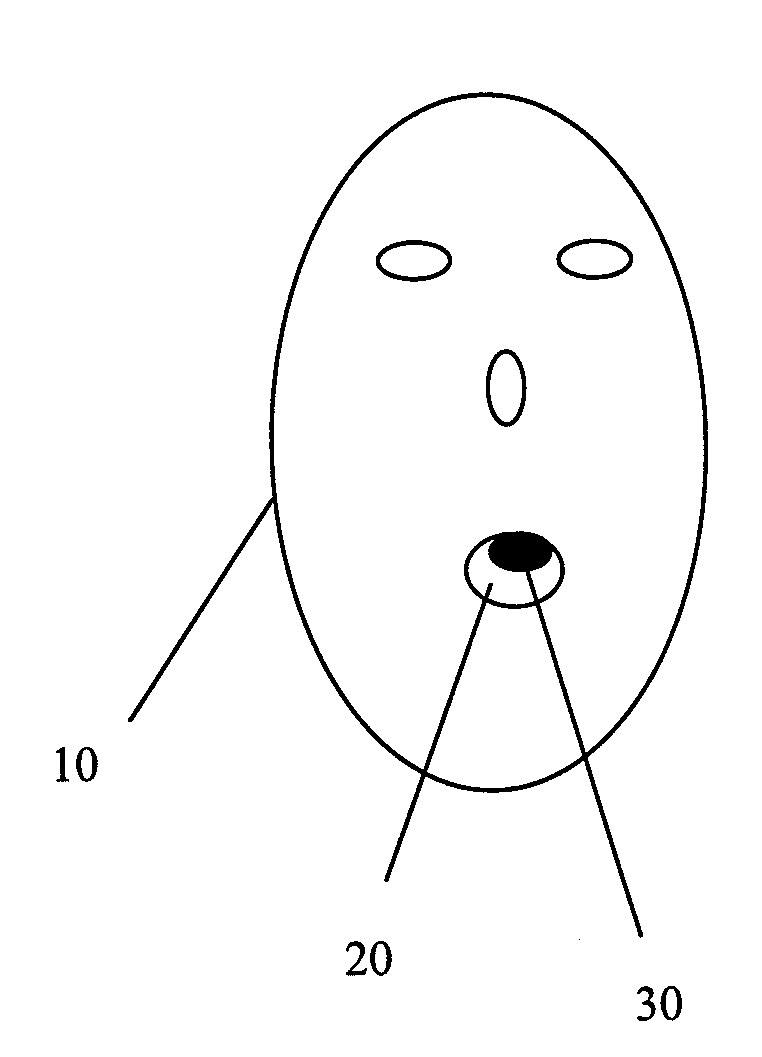
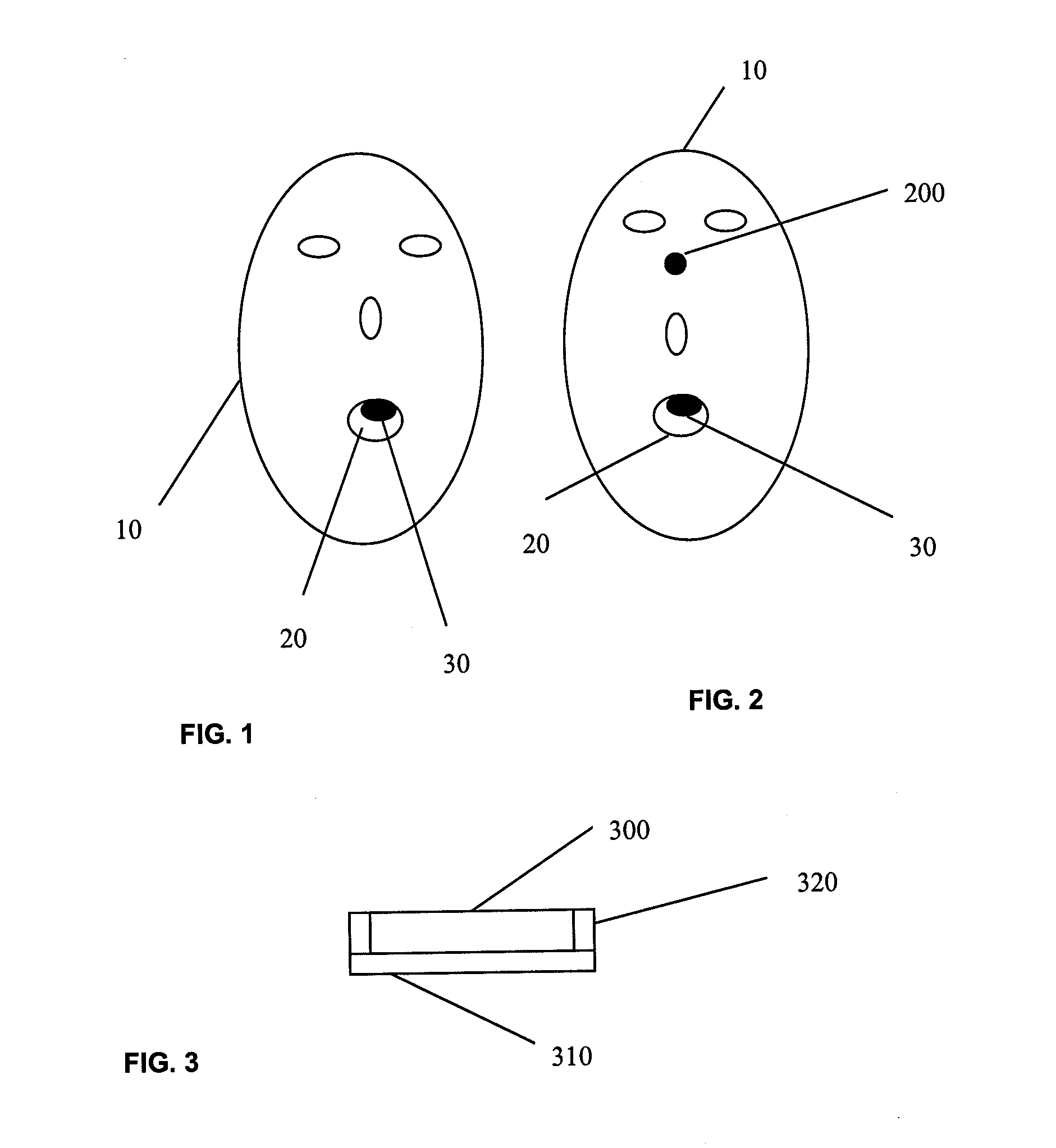
[0032]Described herein are systems and methods for Transcranial Magnetic Stimulation (TMS) using one or more shielding enclosures that may be placed at least partially over a TMS electromagnet to prevent undesirable stimulation of non-target regions behind or next to the TMS electromagnet. In general, a shielding enclosure is configured to at least partially enclose or cover a TMS electromagnet, and includes a back (and may include sides and optionally a front cover). The shielding electromagnet if formed of a material that can reflect and / or channel and / or attenuate the magnetic field emitted by the TMS electromagnet enclosed therein. The shielding enclosure may be part of a system including a plurality of electromagnets, and one or more of the electromagnet may be at least partially enclosed within the shielding enclosure.

[0033]As mentioned above, the shielding enclosure may protect adjacent patient tissues, including regions behind or next to the TMS electromagnet. This may allow...


PUM


Abstract

System and methods for Transcranial Magnetic Stimulation (TMS) are described in which regions adjacent (e.g., to the sides and behind the TMS electromagnet) are protected from the high magnetic fields emitted by the TMS electromagnet. Thus, adjacent muscle or neural structures are protected and undesirable side effects are avoid or minimized, allowing stimulation from previously unavailable sites such as the mouth and pharynx.

Description

CROSS REFERENCE TO RELATED APPLICATIONS[0001]This patent application claims priority to U.S. Provisional Patent Application Ser. No. 60 / 983,140, filed on Oct. 26, 2007, titled “TMS WITH PROTECTION OF MAGNET-ADJACENT STRUCTURES,” which is herein incorporated by reference in its entirety.INCORPORATION BY REFERENCE[0002]All publications and patent applications mentioned in this specification are herein incorporated by reference in their entirety to the same extent as if each individual publication or patent application was specifically and individually indicated to be incorporated by reference.FIELD OF THE INVENTION[0003]The devices and methods described herein relate generally to delivery of magnetic fields to stimulate target brain regions using Transcranial Magnetic Stimulation while protecting adjacent or nearby non-target regions.BACKGROUND OF THE INVENTION[0004]Transcranial Magnetic Stimulation (TMS) has been previously delivered from electromagnets that have been located at one ...

Claims


Application Information

Patent Timeline
Patent Type & Authority Applications(United States)
IPC IPC(8): A61N2/02
CPCA61N2/02A61N2/006
Inventor MISHELEVICH, DAVID JSCHNEIDER, M. BRET
Owner CERVEL NEUROTECH
Learn More