
Reliable network streaming of a single data stream over multiple physical interfaces

Active Publication Date: 2010-11-11
CANON KK
View PDF75 Cites 40 Cited by
  • Summary
  • Abstract
  • Description
  • Claims
  • Application Information

AI Technical Summary

Benefits of technology

[0006]With such an architecture, the single data stream is split into sub-streams and sent over multiple physical interfaces which connect the endpoints of the network, instead of streaming data over only one of the possible physical interfaces. This solution is more flexible and resilient to network load or impairments because multiple physical interfaces are used simultaneously.
[0018]According to an additional aspect, in the case where the sending endpoint and the receiving endpoint each have multiple physical interfaces connected to each of the multiple networks, the designated receive-side physical interface is designated based on a data capacity throughput of the multiple physical interfaces of the receiving endpoint connected to a same network as the designated send-side physical interface, and a data capacity throughput of the designated send-side physical interface. Because the designated receive-side physical interface is designated based on a data capacity throughput of the multiple physical interfaces of the receiving endpoint, the single data stream may be streamed over the multiple physical interfaces with high efficiency.

Problems solved by technology

However, using dissimilar physical interfaces raises a new set of problems.
One of such problems is that a sending endpoint of the network will need to split the data stream into multiple data streams and send the multiple data streams over the multiple physical interfaces in an efficient manner.
Another such problem is that a receiving endpoint will need to reconstruct the multiple data streams into a single data stream.

Method used


Image

  • Reliable network streaming of a single data stream over multiple physical interfaces
  • Reliable network streaming of a single data stream over multiple physical interfaces
  • Reliable network streaming of a single data stream over multiple physical interfaces

Examples


Embodiment Construction

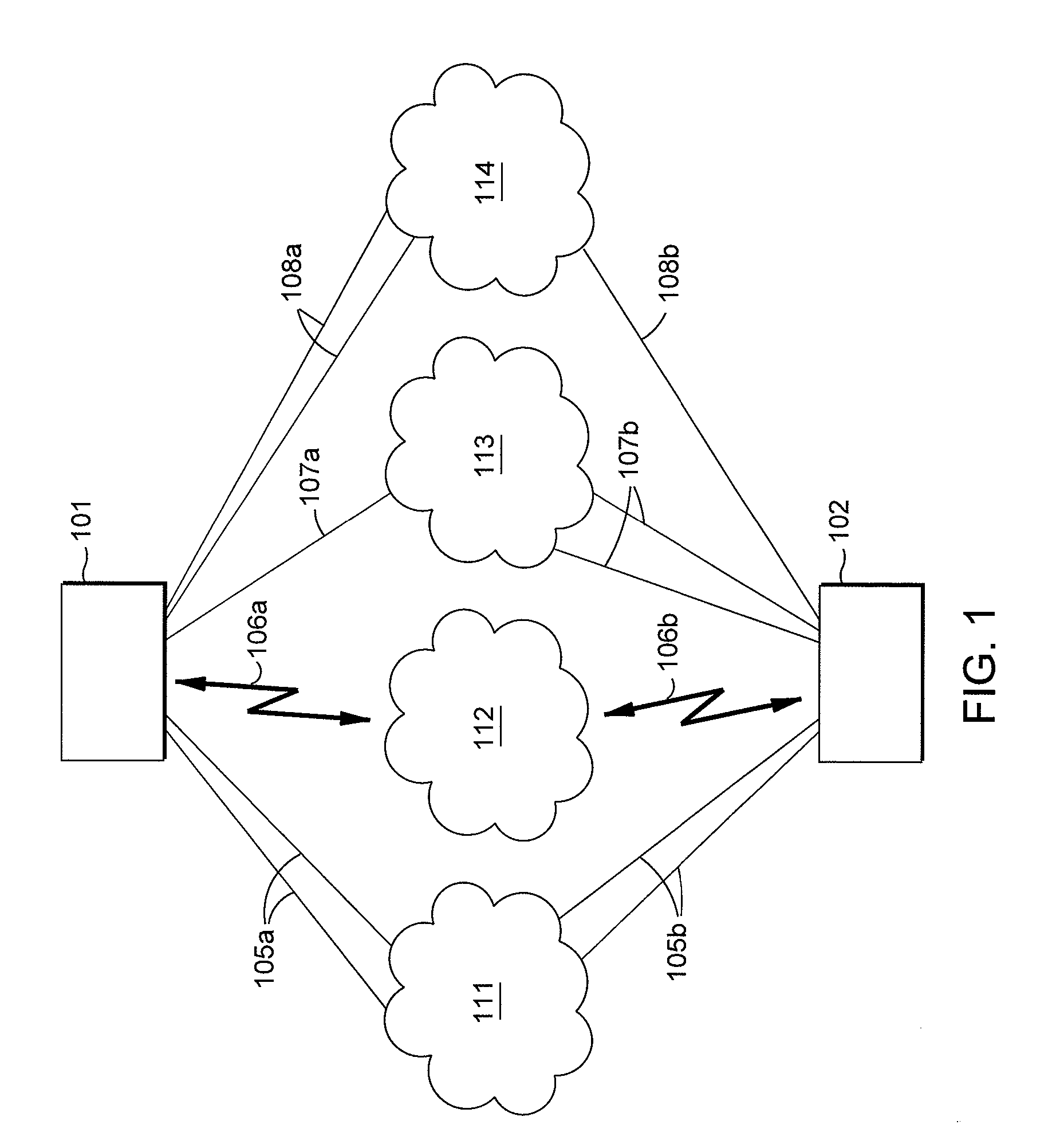
[0044]FIG. 1 is a representative view of a sending endpoint and a receiving endpoint, connected via multiple networks, on which an architecture of an example embodiment may be implemented. As shown in FIG. 1, sending endpoint 101 is connected to receiving endpoint 102 through networks 111, 112, 113 and 114. The networks may include similar or dissimilar networks, mixed in any combination, as described below. Sending endpoint 101 includes multiple physical interfaces, including at least one or more physical interface for each different network. As shown in the example of FIG. 1, sending endpoint 101 includes physical interfaces 105a, 106a, 107a and 108a. More specifically, sending endpoint 101 has physical interfaces 105a which connect sending endpoint 101 to network 111. In FIG. 1, sending endpoint 101 is shown to have two physical interfaces 105a connecting to network 111; however, in other embodiments, sending endpoint 101 may have a single physical interface connecting to network...


PUM


Abstract

Sending a single data stream from a sending endpoint to a receiving endpoint, wherein both of the sending endpoint and the receiving endpoint each have multiple physical interfaces connecting the sending and receiving endpoint to multiple networks, respectively, is provided. The single data stream is partitioned into multiple data packets. A physical interface is designated on the sending side and the receiving side in accordance with a data capacity throughput of each of the multiple physical interfaces. Different portions of the partitioned data packets are then sent over different ones of the multiple physical interfaces in accordance with the designation. The single data stream is then reconstructed by combining received partitioned data packets into the single data stream in accordance with header information. An acknowledgment is sent to the sending endpoint indicating an amount of data received on each multiple physical interface, including any changes in the data capacity throughput.

Description

BACKGROUND[0001]1. Field[0002]The present disclosure generally relates to streaming of data, and more specifically relates to network streaming of data from a sending endpoint to a receiving endpoint.[0003]2. Description of the Related Art[0004]In the field of data streaming in a network, there is a problem in that data streaming from a sending endpoint to a recipient endpoint may be detrimentally affected by limited network bandwidth, collisions in data transmission, and latency, which in turn affect the delivery quality of the streamed data. In the future, network bandwidth will invariably increase; however, recent history has shown that the quantity of data information that needs to be sent over networks grows much faster than the then-current delivery infrastructure. As the quantity of data information continues to increase (e.g., High Definition video streaming), an already overburdened system may provide less than adequate data delivery and / or playback quality, or may fail out...

Claims


Application Information

Patent Timeline
IPC IPC(8): H04L12/26
CPCH04L65/602H04L65/604H04L65/608H04L69/14H04L67/303H04L69/22H04L65/80H04L65/764H04L65/762H04L65/65
Inventor MARTINEZ, MARTINRIGGERT, ERIC
Owner CANON KK
Learn More