Lift lever crown cap system and method

a technology of lever crown cap and lever head, which is applied in the direction of caps, applications, liquid handling, etc., to achieve the effects of low manufacturing cost, convenient and efficient manufacturing and marketing, and durable and reliable construction

Inactive Publication Date: 2010-11-11
SUPER CLOSURE INT
View PDF23 Cites 24 Cited by
  • Summary
  • Abstract
  • Description
  • Claims
  • Application Information

AI Technical Summary

Benefits of technology

[0012]The crown cap is positioned over the top of the bottle. The inverted U-shaped projection is located above the lip of the bottle. The V-shaped projection is located radially inward of the top of the bottle. The side wall of the crown cap is crimped. The ledge of the crown cap is provided beneath and in continuous contact with the outwardly extending projection of the bottle. In this manner a tamper evident-secure lock band is provided. Further in this manner the body strength of the bottle is increased and evidence of tampering is provided.
[0019]It is therefore an object of the present invention to provide a new and improved lift lever crown cap system which has all of the advantages of the prior art closure systems of known designs and configurations and none of the disadvantages.
[0020]It is another object of the present invention to provide a new and improved lift lever crown cap system which may be easily and efficiently manufactured and marketed.
[0021]It is further object of the present invention to provide a new and improved lift lever crown cap system which is of durable and reliable constructions.
[0022]An even further object of the present invention is to provide a new and improved lift lever crown cap system which is susceptible of a low cost of manufacture with regard to both materials and labor, and which accordingly is then susceptible of low prices of sale to the consuming public, thereby making such lift lever crown cap system economically available to the buying public.
[0023]Even still another object of the present invention is to provide a lift lever crown cap system for forming a pour through top opening in a crown cap crimped onto a bottle, such forming of an opening being done in a safe, ecological, convenient and economical manner.

Problems solved by technology

While these devices fulfill their respective, particular objectives and requirements, the aforementioned patents do not describe a lift lever crown cap system that allows for forming a pour through top opening in a crown cap crimped onto a bottle, such forming of an opening being done in a safe, ecological, convenient and economical manner.

Method used


Image

  • Lift lever crown cap system and method
  • Lift lever crown cap system and method
  • Lift lever crown cap system and method

Examples


Embodiment Construction

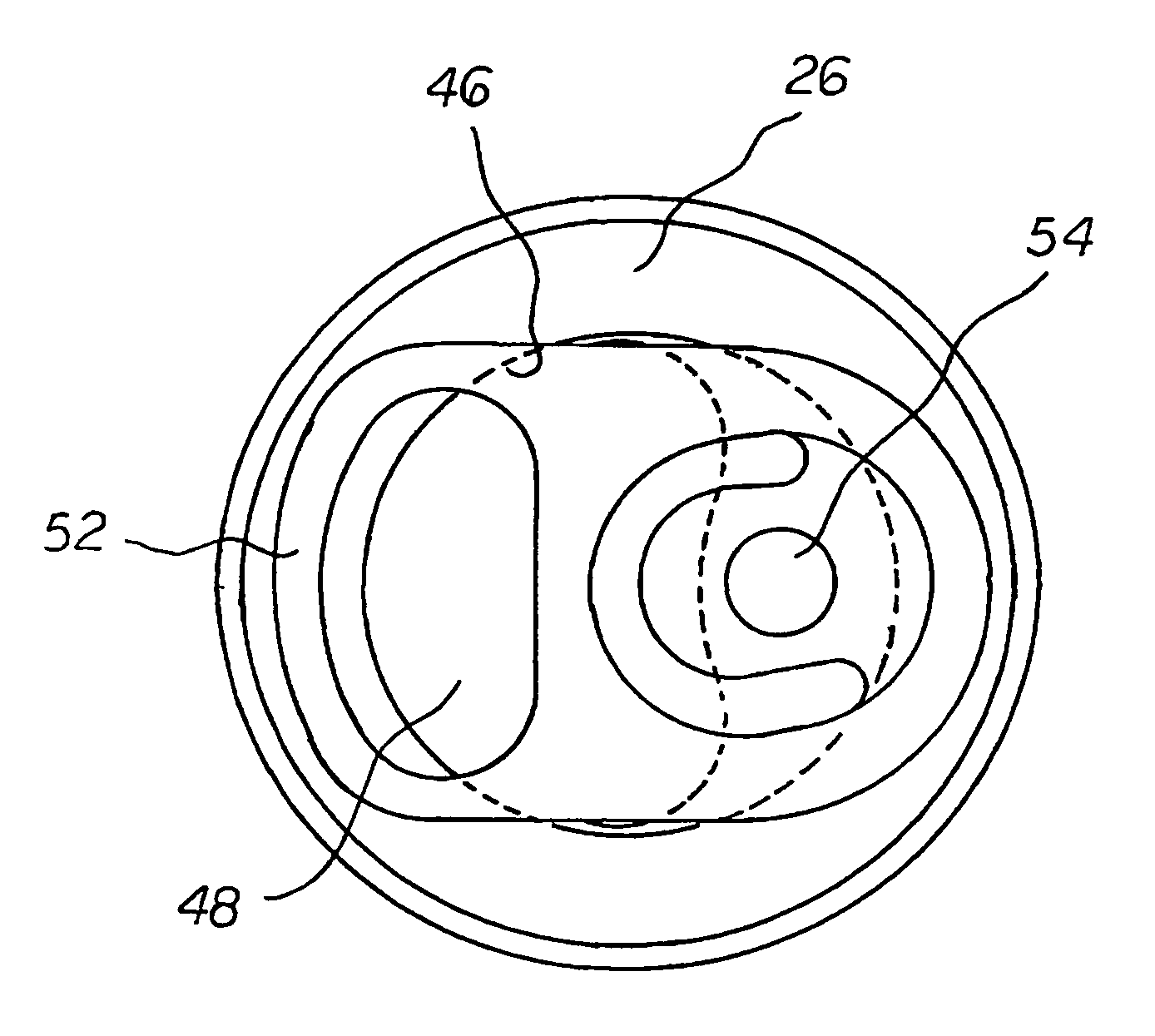
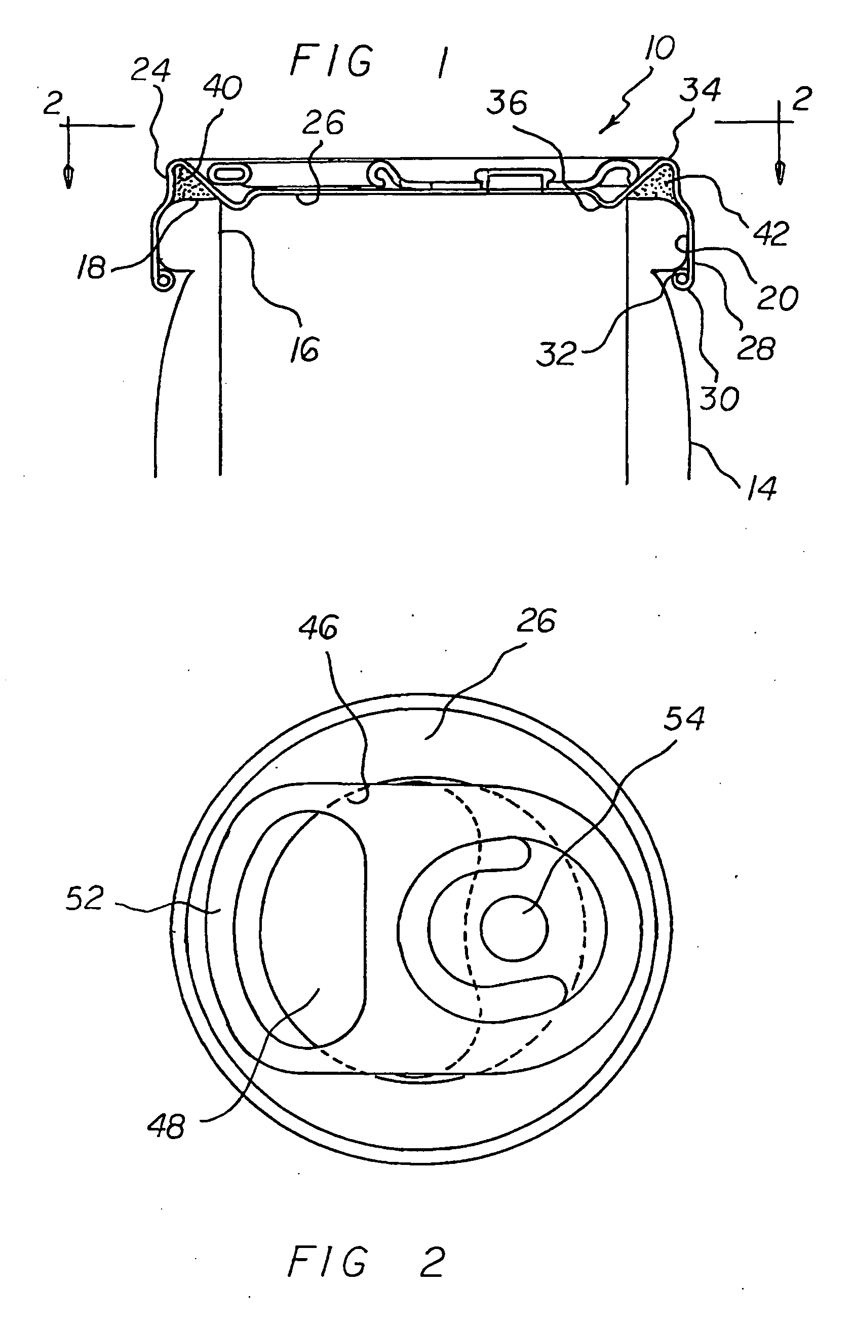
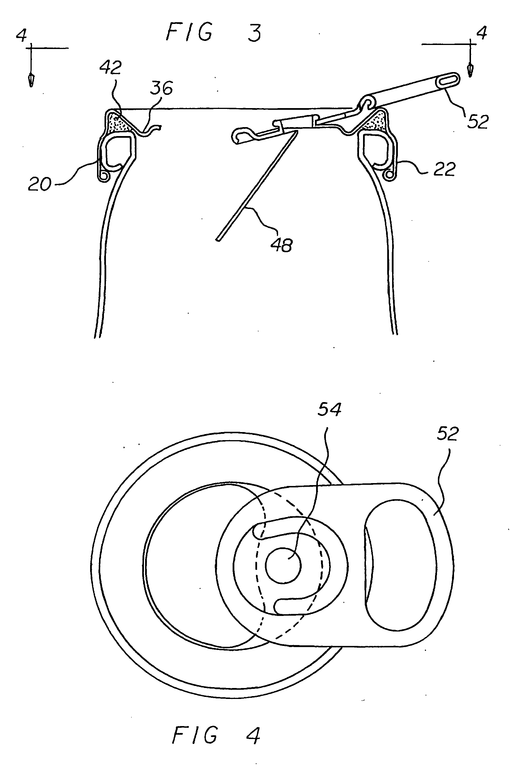
[0034]With reference now to the drawings, and in particular to FIG. 1 thereof, the preferred embodiment of the new and improved lift lever crown cap system embodying the principles and concepts of the present invention and generally designated by the reference numeral 10 will be described.

[0035]The present invention, the lift lever crown cap system 10 is comprised of a plurality of components. Such components in their broadest context include a crown cap, a score line, and a lift lever. Such components are individually configured and correlated with respect to each other so as to attain the desired objective.

[0036]First provided is a bottle 14 for containing a liquid. The bottle has a generally cylindrical body. The bottle has an open top 16. The open top has a circular lip 18. The bottle has an axially spaced, outwardly extending projection 20. The lip is provided above the projection. The lip is provided in a horizontal plane at an elevation above a plane containing the outwardly ...


PUM

PropertyMeasurementUnit
corrosiveaaaaaaaaaa
non-corrosiveaaaaaaaaaa
body strengthaaaaaaaaaa

Abstract

A crown cap is couplable to a container. The crown cap has a central region and a downwardly extending side wall. At least one score line is in a geometric configuration on the central region of the crown cap. The at least one score line forms a tongue. The tongue is adapted to be bent or hinged downwardly. In this manner a passageway is provided for a liquid. A lever is coupled to the crown cap. A post extends through the lift lever and the central region of the crown cap. A tamper-evident secure band is designed into the side wall of the crown cap. A non-corrosive material is used to form the crown cap, lever and attachment post.

Description

BACKGROUND OF THE INVENTION[0001]1. Field of the Invention[0002]The present invention relates to a lift lever crown cap system and method and more particularly pertains to forming a pour through top opening in a crown cap crimped onto a bottle, such forming of an opening being done in a safe, ecological, convenient and economical manner.[0003]2. Description of the Prior Art[0004]The use of closure systems of known designs and configurations is known in the prior art. More specifically, closure systems of known designs and configurations previously devised and utilized for the purpose of closing containers through known methods and apparatuses are known to consist basically of familiar, expected, and obvious structural configurations, notwithstanding the myriad of designs encompassed by the crowded prior art which has been developed for the fulfillment of countless objectives and requirements.[0005]By way of example, U.S. Pat. No. 6,109,465 issued Aug. 29, 2000 to Henning relates to ...

Claims


Application Information

Patent Timeline
Patent Type & Authority Applications(United States)
IPC IPC(8): B65D41/42B21D31/00
CPCB65D17/165B65D41/42B65D2517/0014B65D2517/0007B65D53/00B65D2543/00425B65D41/12B65D17/4012B65D2401/00B65D41/125B65D41/28B67B7/16
Inventor GILLIAM, JAMES R.
Owner SUPER CLOSURE INT
Why Eureka
Try Eureka